GEAR DESIGN AND ANALYSIS
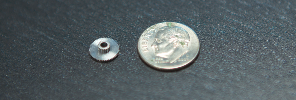
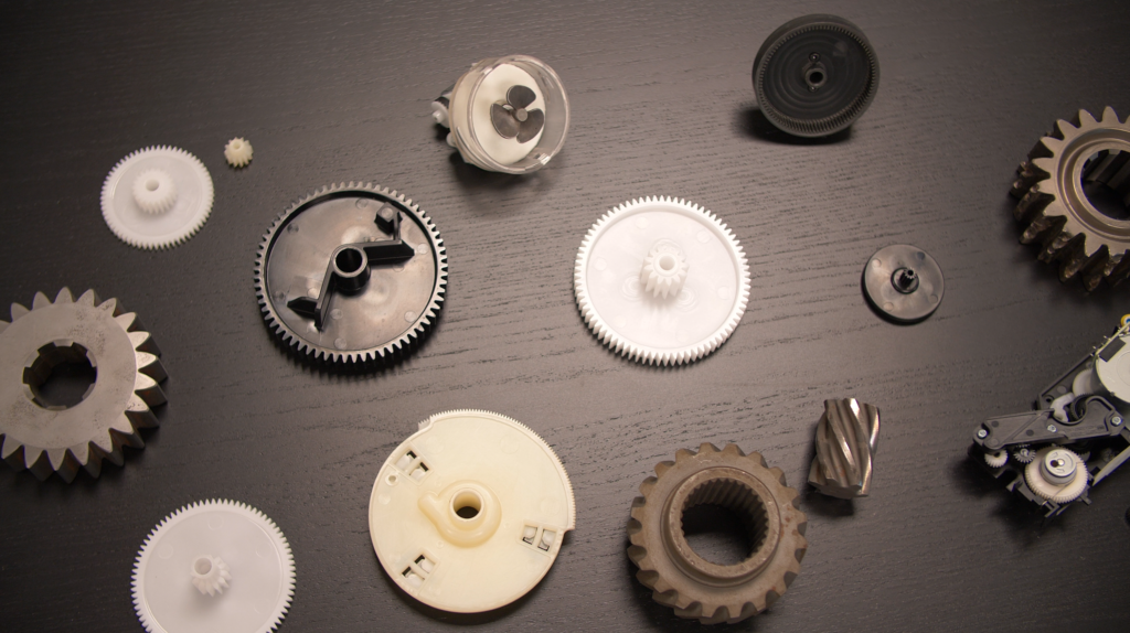
Engineers at Simplexity have designed gears from high horsepower automotive street & racing transmissions (up to 4.5 Module gears) to micro MIM and plastic gears (down to 0.15 Module gears) for small consumer products. Over a number of years, our team of gear design analysis experts at Simplexity developed an easy to use yet very powerful proprietary gear design tool, called the Simplexity Gear Design ProTM. It rivals the power of commercially available design packages at a fraction of the cost while gaining our engineers the flexibility to change and update the tool depending upon the client’s needs. For example, we recently added limited involute spline and bevel gear design capabilities based upon a client’s needs.
Basic Design Modes: The most common gears designed are plain spur gears but the Simplexity Gear Design ProTM can also design rack & pinion drives, internal spur gear rings, helical gears, non-enveloping worm & worm gear pairs, and bevel spur gears. These all can be designed as fully custom modules and pressure angles to meet any specific need (typically these are molded or wire cut types of gears) or they can be designed such that they meet a very specific client need while being able to be machined using common off-the-shelf tools.
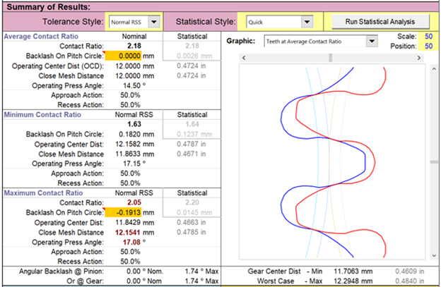
System Approach: As with our other design expertise, we look at the gear train as a system to optimize more than just evaluating the gear ratio. The design tool incorporates a Monte Carlo style tolerance analysis system to consider not only the gear manufacturing tolerances but also the variation around how the gears are mounted and are aligned to each other. This analysis not only includes the normal mechanical tolerances but also includes material attributes for temperature and humidity effects. The Simplexity Gear Design ProTM automatically generates data for nominal, minimum, or maximum contact ratio conditions.
Quality: Presently the quality system built into the design tool is based upon the AGMA 2000 standards. We have worked with the AGMA 2015, JIS 1998, JIS 2016 and current ISO/DIN standards. We understand the various quality levels, how they affect performance, part cost, and manufacturing requirements. Our team has been involved with high volume manufacturing of high precision (AGMA Q14C molded plastic gears at 0.5 Mod) down to low volume cut or ground tooth form steel gears for decades.
Data Exchange with 3D CAD: The Simplexity Gear Design ProTM can export the tooth form information for direct import into either SolidWorks or Creo Elements Direct. This tooth form information can be exported in three states: average or nominal contact ratio conditions, minimum contact ratio conditions, or maximum contact ratio conditions. This allows for 3D modeling or 3D finite element analysis (FEA) at the tolerance extremes. Molded or machined gears can be manufactured directly from this 3D CAD.
Gear Manufacturing Data Exchange with 2D CAD: The Simplexity Gear Design ProTM can directly export a variety of gear chart styles (gear type & manufacturing method specific) to be inserted into CAD drawings.
Tooth Form: The Simplexity Gear Design ProTM allows for use of a large number of standard tooth forms (AGMA full fillet root, ISO 53-A, PGT-1 thru 4, etc), which allows the user to modify the tooth thickness, major & minor diameter, root radius and tip radius all independently depending upon the needs. The Simplexity Gear ProTM also has some standard tip relief forms built in for use with lower stiffness materials or highly stressed gear pairs.
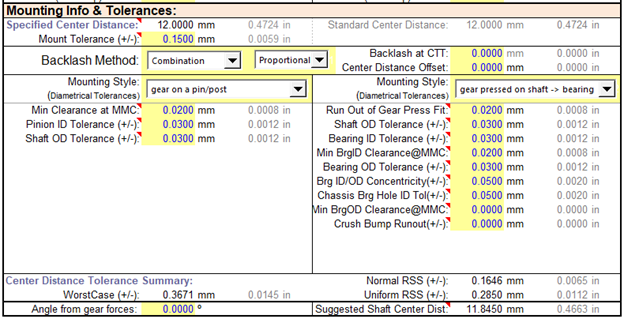
Center to Center distance and Mounting Styles: The Simplexity Gear Design ProTM allows the designer to specify any desired center to center distance. The Simplexity Gear Design ProTM includes a number of standard mounting styles plus a fully custom style to guide the user for all potential tolerances.
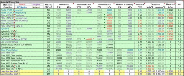
Materials: The Simplexity Gear Design ProTM contains a local materials database which can be easily updated or modified by the end user. A partial sample of the database is shown below.
Backlash: The Simplexity Gear Design ProTM not only calculates tooth to tooth backlash at the three contact ratio conditions, but also contains methods to assist the designer in modifying the backlash amount.
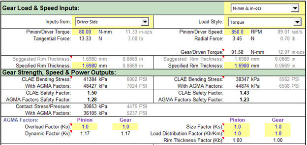
Strength: The Simplexity Gear Design ProTM allows for the input of various loads that can output the strength calculation based upon the Lewis tooth form calculations. Results have been validated for a variety of tooth forms and materials thru the use of FEA. This allows for very quick feedback on a tooth design with respect to strength. The contact stress is also calculated using standard AGMA formulas.
Speed & Frequency: Various pitch line velocities and output frequencies are calculated.
Friction, Wear & Efficiency: Using various coefficient of friction (COF) factors and tooth forms the Simplexity Gear Design ProTM uses published AGMA formulas to calculate the gear pair efficiency. Using the contact stress, PV (pressure times velocity) is calculated which is especially important in the design of plastic gears. Approach action, recess action, hunting and assembly modes are also calculated.
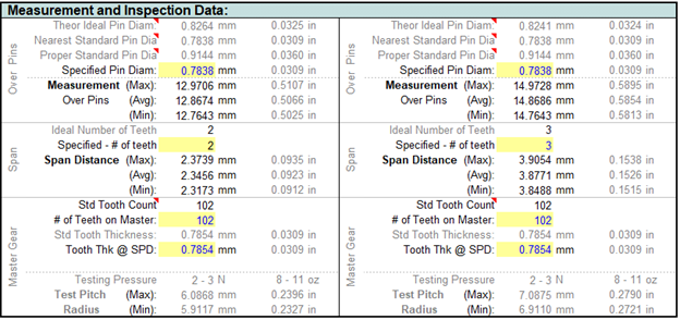
Inspection Data: In addition to the AGMA Quality standards, a variety of industry standard methods are calculated to assist the manufacturer to inspect the gears to ensure they meet the desired specification.
Reverse Engineering: The Simplexity Gear Design ProTM contains a number of auxiliary calculations to reverse engineer existing gears to quickly get their data into the Simplexity Gear Design ProTM for analysis and updates as necessary.
Additional Features: Additional tools are including to aid the designer to select tooth counts vs gear ratio and center distance, when working with bevel gears and when designing planetary gear set.


