logo

ISO 13485:2016
Certified Product
Development

Main Menu
  • About
    • Philosophy
    • Team
    • Company History
    • Awards
    • Core Values
    • Careers
  • Portfolio
    • Robotics & Automation
    • Biotech
    • Consumer Devices
    • Wearables
    • Medical Devices
    • Artificial Intelligence (AI)
    • Commercial Equipment
    • Test Fixtures
  • Disciplines
    • Mechanical Engineering
    • Electrical Engineering
    • Firmware Engineering
    • Software Engineering
    • Systems Engineering
    • Project Management
    • Manufacturing Engineering
    • Quality Engineering
    • Prototyping
    • New Product Introduction
  • Services
    • Full System Product Development
    • Product Simplification and Cost Reduction
    • Product Feasibility Assessments
    • Product Development Research
    • Product Requirements and Architecture Explorations
    • Prototype Development and Optimization
    • Integrated Engineering Services
    • Product Quality Management
    • Design for Manufacturing (DfM)
    • Design for High Volume Manufacturing
  • Expertise
    • Mechatronics
    • Printer Development
    • Test Tool Development
    • Cost Reduction and Simplification
    • Power Management
    • Gear Design and Analysis
    • Fluidics and Microfluidics Management
    • Internet of Things (IoT)
    • Design for Harsh Environments
    • Embedded Motion Solutions
  • Resources
    • Product Development Process
    • Quality and Regulatory
    • ISO Certification
    • Engineering and NPI Templates
    • Blog
    • Videos
    • Webinars & Podcasts
    • News & Events
    • Publications
  • Contact Us
Search icon X

Mechatronics & Robotics

WHY YOU NEED A GYRO TO MEASURE POSITION

January 20, 2017 | by Doug Harriman

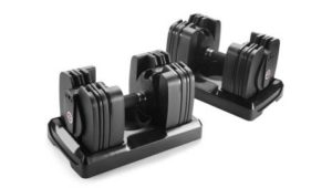
The Bowflex SelectTech 560® (ST560) is a “smart” dumbbell, a piece of exercise equipment with embedded sensors and processing to provide training feedback during your workout.  The ST560 has an… Read More

Categories: Engineering & Analysis, Firmware & Software, Electrical Engineering, Mechatronics & Robotics

MECHATRONICS AIDS IN EMBEDDED SYSTEM DESIGN

December 7, 2016 | by Doug Harriman

Over the last few years, a lot has been written about the future of computing as centered around “big data” algorithms running on servers in data centers. However, embedded systems… Read More

Categories: Product Development & Design, Mechatronics & Robotics

WHEN SHOULD YOU CONSIDER DESIGNING CUSTOM GEARS?

November 7, 2016 | by Michael Allison

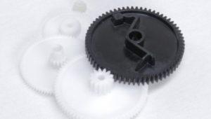
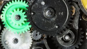
There are typically a number of considerations when choosing whether you want to use a stock gear or to design a custom gear. Two of the key considerations are cost… Read More

Categories: NPI (New Product Introduction), Engineering & Analysis, Mechanical Engineering, Prototyping & Manufacturing, Mechatronics & Robotics

WHAT IS A MOTION CONTROL SYSTEM?

October 20, 2016 | by Doug Harriman

motion control system

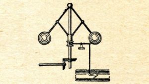
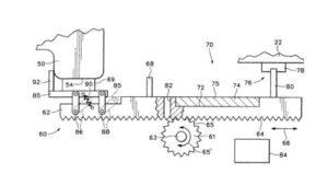
What is a Motion Control System? At the most fundamental level, a motion control system is any system that controls energy flow to generate mechanical motion with some desired properties…. Read More

Categories: Engineering & Analysis, Firmware & Software, Electrical Engineering, Mechatronics & Robotics

WHAT IS THE MECH IN MECHATRONICS?

August 16, 2016 | by John Pruyn

Mechatronics is not only about the motor, but rather getting the most out of the motors you have. To do that you have to step back and look at the… Read More

Categories: Mechanical Engineering, Prototyping & Manufacturing, Mechatronics & Robotics

SELECTING THE CORRECT MOTOR TYPE AND SIZE

June 6, 2016 | by Bob Callaway

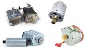
What is the correct (or best) motor to use in a motion control application? Given the myriad choices of type, size and performance it should not be surprising that there… Read More

Categories: Prototyping & Manufacturing, Mechatronics & Robotics, NPI (New Product Introduction), Product Development & Design, Mechanical Engineering, Electrical Engineering

FIVE TIPS FOR MECHATRONIC SYSTEM INTEGRATION

May 9, 2016 | by Doug Harriman

mechatronic system integration

In part two of my three-part mechatronics discussion I provided tips for the design of high volume mechatronic systems. In this final entry of the series, I’ll discuss five additional tips… Read More

Categories: Product Development & Design, Mechatronics & Robotics, Simplification

THREE TIPS FOR DESIGNING HIGH VOLUME MECHATRONIC PRODUCTS

April 28, 2016 | by Doug Harriman

As I discussed in part one of my three-part mechatronics discussion, there are many, many types of mechatronics systems in the world. In industry, the largest market segment that would clearly identify… Read More

Categories: Prototyping & Manufacturing, Mechatronics & Robotics, Simplification, NPI (New Product Introduction)

WHAT IS MECHATRONICS?

April 18, 2016 | by Doug Harriman

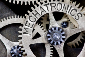
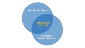
The word “mechatronics” was first coined in Japan in the late 1960’s to refer to the synergistic blend of mechanics and electronics. The word has evolved to describe products and… Read More

Categories: Product Development & Design, Mechatronics & Robotics

  • « Previous Page
  • 1
  • 2
  • 3

Categories

  • Simplification
  • Events & Tradeshows
  • NPI (New Product Introduction)
  • Engineering & Analysis
  • Biotech
  • Product Development & Design
  • Medical
  • Molecular Diagnostics
  • Connected Consumer
  • Commercial Equipment
  • Wearables
  • Industry Trends, IoT, AI, VR, & AR
  • Leadership & Business
  • Firmware & Software
  • Mechanical Engineering
  • Electrical Engineering
  • Prototyping & Manufacturing
  • Mechatronics & Robotics

Recent Posts

  • ROBOTICS, AI, AND TACTILE TECH: POWERFUL INSIGHTS FROM THE 2025 ROBOTICS SUMMIT
  • FROM GEARS TO INTELLIGENCE: THE EVOLUTION OF MECHATRONICS AND ROBOTICS
  • DIGILENT ANALOG DISCOVERY PRO 3250
  • BLENDJET 2 PORTABLE BLENDER TEARDOWN
  • USING AUTOMATION TO REALIZE THE DREAM OF “FAST, CHEAP, AND GOOD”

Offices:

San Diego, California
Portland, Oregon Area
Seattle, Washington

Contact Us

Connect:

Careers at Simplexity
Employment Verification
Join our Mailing List!
Privacy Policy
Simplexity Product Development
Copyright © 2025 | All Rights Reserved

Phase 3: Design Verification And Design Transfer

Design & Engineering

Software: Design Complete
Hardware: Pre-production units for design verification
Test: Design verification test

NPI

MFG. Readiness: CM schedule and budget, Unit build tracking
Quality: Quality metrics verification process, Process validation support

This phase occurs once the detailed design is complete, and prototypes are built with manufacturing-representative quality and detail. More extensive, formal testing is performed, such as life, reliability, safety, environmental, drop, and vibration.

The design team works closely with the manufacturing team to enable a smooth transfer, often with Simplexity engineers traveling to the contract manufacturer sites to ensure product quality. The design is transferred to the client based upon specific needs, most often after all tests are complete and the design is verified.

Typical deliverables:

  • Pre-production units
  • Formal verification test reports
  • Design transfer package, including Design History File (DHF) if needed for FDA submittal
  • Process validation support
  • Unit build tracking
  • Contract manufacturing schedule and budget
  • Quality metrics verification

Gate definition:

  • Design verification complete

Phase 2C: Detailed Design Prototype 2

Design & Engineering

Software: Full feature implementation
Hardware: Prototype 2 units with production-representative materials and processes
Test: Engineering confidence test, integration test

NPI

MFG. Readiness: CM onboarding Design transfer prep
Quality: Build Quality Plan

2C. Prototype 2 Design, Build And Test

Phase 2C iterates on the learnings of Phase 2B and involves a refined prototype build of a fully integrated system. Some projects also benefit from additional iterations of the product based on prior learnings through additional phases (2D, 2E, etc), which are not represented in this graphic.  All requirements are intended to be tested, and at the end of Phase 2 there will be confidence that the units will pass verification in Phase 3.  The Bill of Materials is further refined, and the team updates estimates for the per unit cost of the product by receiving pricing from vendors and suppliers.

Typical deliverables:

  • Updated prototypes
  • Software and/or firmware binaries and source code
  • Updated schematics and layout
  • Updated 3D CAD files and 2D drawings
  • Verification/test plans and reports
  • Updated Bill of Materials (BOM) and Cost of Goods Sold (COGS)
  • Build Quality Plan development
  • Design transfer preparation
  • Contract Manufacturer onboarding

Gate definition:

  • Engineering confidence test reviews (integration tests)

Phase 2B: Detailed Design

Design & Engineering

Software: Core functionality implementation
Hardware: Prototype 1 units with rapid prototyped components
Test: Engineering confidence test, unit test

NPI

MFG: Readiness: Project build plan CM selection
Quality: Critical manufacturing process identification

2B. Prototype 1 Design, Build And Test

The detailed design phase usually has multiple, iterative sub-phases as the design progresses and representative prototypes are built. Phases 2B and 2C are typically the largest efforts in the product development process, where the specific implementation for all disciplines occurs (mechanical, industrial design, electrical, firmware, systems, software, manufacturing, and quality).

Simplexity typically engages with production component suppliers and contract manufacturing groups early in this phase to provide additional manufacturing input on the design. If the product has stringent testing or certification requirements, pre-screens are performed in this phase prior to formal regulatory agency testing.

Typical deliverables:

  • Prototypes (3D printed or other rapid prototypes, electrical PCAs, and/or preliminary code)
  • Software and hardware design documentation
  • Initial product firmware or software binaries and source code
  • Electrical schematics and layout
  • 3D CAD files
  • Design failure mode and effect analysis
  • Test plans and reports
  • Project build plan – from prototype to pre-production
  • Initial Bill of Materials (BOM) and Cost of Goods Sold (COGS)
  • Manufacturing process identification
  • Contract Manufacturer (CM) selection

Gate definition:

  • Engineering confidence test reviews

Phase 1: Requirements & Planing

Design & Engineering

Project Plan Requirements
ID/UX Concepts
Risk Analysis
Manufacturing Strategy Identification
 

The business and user requirements are converted into engineering requirements for the product. The project planning activity is based on the schedule, budget, risk, and initial product requirements. This process is best done as a collaborative team effort with the client, who has the deepest understanding of the market needs and user requirements.

Typical deliverables:

  • Product requirements document
  • Project development plan (including plans for software/firmware electrical, quality, systems, and mechanical)
  • Risk analysis
  • Industrial Design (ID) and User Interface (UI) concepts

Gate definition:

  • Product requirements document complete
  • Client approval of project development plan

Production

Design & Engineering

Manufacturing design guidance and ongoing engineering support
Ongoing quality metrics monitoring & optimization

The Simplexity team can be as involved in the production phase as requested by our clients. For clients with internal manufacturing or established relationships with contract manufacturers, our engineers are available to ensure quality is maintained and provide ongoing engineering support as needed.

Simplexity has a dedicated New Product Introduction (NPI) team that can guide the transition from design into production. The NPI team presents multiple options for manufacturing to the client, allowing clients to choose the solution that best suits their needs.  This can involve Simplexity performing initial builds in-house prior to full handoff to a contract manufacturer or building the product via established relationships with contract manufacturing partners either domestically or overseas early in the process.

Typical deliverables:

  • Manufacturing guidance and ongoing engineering support
  • Ongoing quality metrics monitoring and optimization

Phase 2: Detailed Design

Design & Engineering

Software: Architecture design: block, sequence and state diagrams
Hardware: Major Component definition & Proof of Concept subsystems build
Test: Characterization and qualification of high risk subsystems & components

NPI

Quality: Design for Manufacturing tradeoffs evaluation

2A. Architecture and Technology Feasability

The detailed design phase starts with defining options for the product architecture, with the goal of having the greatest chance of successfully meeting product requirements while best mitigating risk. Engineering activities in this phase include presenting options for hardware components, outlining the system block, sequence, and state diagrams, creating rough CAD, and breadboarding of high-risk subsystems. Results are presented with a description of the pros, cons, and key tradeoffs for each scenario.

Typical deliverables:

  • System architecture design (including mechanical, electrical and software/firmware)
  • Initial product risk analysis
  • Breadboards or proof-of-concept prototypes of high-risk technologies or subsystems.
  • ID concept models

Gate definition:

  • Client approval following hardware and software architecture reviews

Phase 0: Exploration

Exploration

Research
Concept Work
Architecture explorations
Feasibility study

Phase 0 is an optional phase for projects where the technical feasibility of the idea has not yet been fully proven. It can consist of research, concept work, exploring initial architecture, performing feasibility studies, and basic prototyping and testing.

Typical deliverables:

  • Exploration report

Gate definition:

  • Client approval on feasibility of idea