Configurations are a powerful tool in SOLIDWORKS which allow users to maintain multiple versions of a part or an assembly in a single file. Like many features in SOLIDWORKS, Configurations are a flexible tool, subject to the preferences of individual designers and companies.
Once a Configuration is created in a part, the designer can set unique dimension values, suppress features, and define Configuration-specific properties like material. (For a full list of configurable items in parts, see the SOLIDWORKS help article here – Configurable Items for Parts – 2021 – SOLIDWORKS Help.)
Here are three examples of when I use SOLIDWORKS Configurations in part design:
1: Working through multiple design paths
At the beginning of the design process or when implementing a design change, it can be useful to try out several different design paths prior to committing to the final design. Using Configurations allows the designer to try multiple design paths without recreating work for each design. Also, keeping the models linked allows changes that impact all the design paths to propagate through without additional work and minimizes the risk that updates are missed. Once a single design path is determined, that design should be incorporated in the Default Configuration and other Configurations should be renamed or deleted to prevent confusion later in the development process.
2: Iterations of the same part
When designing a system where several different parts are interchangeable, like an impact tester with three different test heads, it can be helpful to design the interchangeable parts as Configurations to a base part. This process also reduces the recreation of work and minimizes the risk that a critical design change to the interface isn’t propagated to all the designs. Once the design is finalized, the parts should be separated out into unique part files so that each part has a unique part number assigned. (This is dependent on how the designer or company does part number management.)
3: Secondary machining of quick-turn or rapid prototype parts
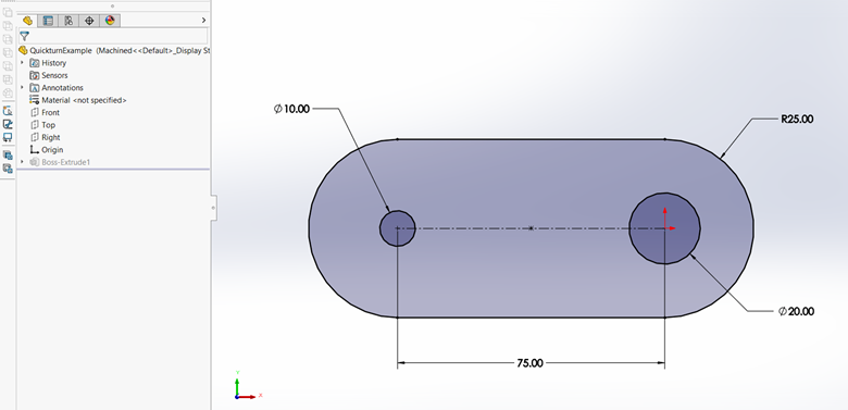
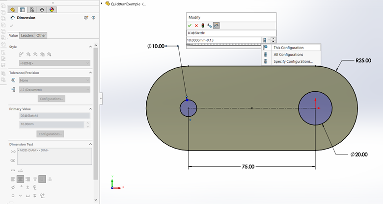
It is often necessary to use a quick-turn or rapid prototype vendors for fabricating the parts needed for a build. These vendors may not offer tolerances that are acceptable on critical holes or features and therefore these features will need to be undersized or oversized to ensure that there is sufficient material for secondary machining in-house. For instance, this part requires a 10 mm +/- 0.01 mm hole for a mating part, but the quick-turn vendor will only guarantee a machining tolerance of +/- 0.13 mm.
Adding a Configuration, called “Quick-Turn” in this example, allows for both the quick-turn part and the final, machined in-house version of the part to be stored in the same file. Create a Configuration and edit the sketch for the hole in question. Select the diameter of the hole in the sketch, undersize it by 0.13 mm, and specify the Configuration that the new dimension applies to (This Configuration, All Configurations, or Specify Configurations). This ensures the hole will be sufficiently undersized to allow the part to be reamed to the correct hole size in-house.
Configurations can also be extremely helpful when used in an assembly. Once a Configuration is created in an assembly, the designer can define Configuration-specific mates, change the suppression state of components and mates, and define the referenced Configuration of components. (For a full list of configurable items in assemblies see the SOLIDWORKS help article here – Configurable Items for Assemblies – 2021 – SOLIDWORKS Help.)
Here are three examples of when I use SOLIDWORKS Configurations in assemblies:
1: Multiple configurations during use
Assemblies can often require multiple configurations during use. For instance, an assembly could have a separate calibration configuration that incorporates tools or fixtures that are not used in the final assembled system. By using Configurations in the main assembly, the tools and fixtures will be captured in the overall bill of materials. Additionally, changes in the final assembly can be reflected in the required tools and fixtures, preventing unintended interferences or mismatching features.
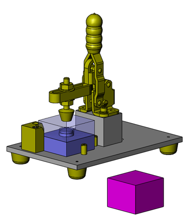
For example, this press-fit fixture requires the pink calibration block be used during calibration but only uses the blue workpieces during normal use (default configuration). The designer can create a Configuration named “Calibration” in the assembly, suppress both blue workpieces, and mate the pink calibration block in the correct orientation for use. It’s important to also check the Default Configuration and ensure the calibration block is suppressed and both workpieces are unsuppressed. While this is a simple example, using this process on complex assemblies can help determine if there are unexpected interferences with the calibration tooling or fixtures.
2: Interference check on dynamic systems
A system that has multiple moving components with a variety of positions can present a challenge when attempting to remove possible interference during the design process. Manually changing mates or moving the components to the correct positions can be cumbersome and inaccurate. To simplify this, Configurations can be created for the specific positions that you are interested in. For a simple linear guide system with two hard stop positions, the designer may be interested in a few key positions such as the minimum position, mid-range of travel position, and the maximum position. Defining Configurations and adjusting the mates for the workpiece will allow the designer to easily switch between positions by switching Configuration and checking for interferences.
3: Modeling different orientations for components
Some assemblies have components that can be in different orientations during use, such as a box with a rotating antenna. Defining a Configuration with the antenna raised and another Configuration with it lowered could be beneficial if the assembly needs to be in a certain orientation for designing a shipping box or another mating component. These Configurations can also be helpful if the designer often needs to include images of the design in the two orientations for reports or presentations.
Using SOLIDWORKS Configurations in your next product design project may help to minimize the amount of redundant work, prevent interferences, and ultimately, save you valuable time. These are just a few examples of what you can do with configurations in SOLIDWORKS and with some use, you will discover your own favorite hacks and best practices that work best for your design process. If you need additional help with your design, please reach out to us. We may be able to help you reduce your cost and simplify your design.

