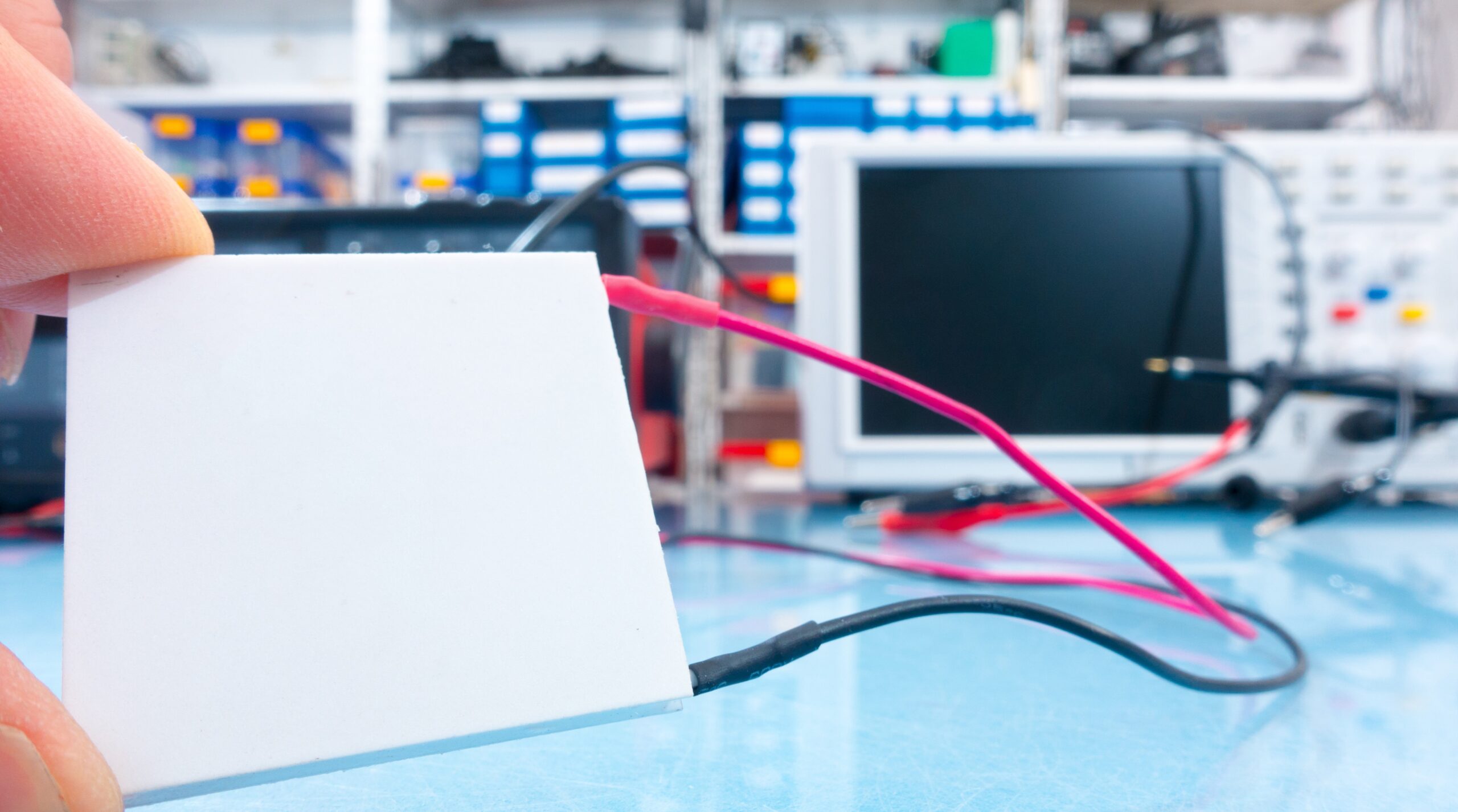
Did you know that you can chill objects below ambient temperature without a refrigerator? This can be done using devices called Thermoelectric Coolers, or TECs. TECs use electricity to move heat from one region to another, similar to a heat pump you might use to heat and cool your home. TECs can both heat and cool a target object, so they are used in a variety of applications that require temperature control such as medical or molecular diagnostics tools, high power electronics, and reagent storage. Additionally, TECs can be quite small, there are no moving parts, and the technology is affordable to be integrated into a number of different products.
Theory of Operation
TECs (also called Peltier Devices) may be purchased off-the-shelf (OTS), customized by a supplier, or purchased as part of a (customized) temperature control module that includes other components. They are commonly used for low/medium heat load applications (hundreds of Watts). Higher heat loads may require compressor-based systems that have a higher Coefficient of Performance or COP. Resistive heaters are often cheaper than TECs, but from the Laird Handbook: TECs when used for heating a target are “more efficient than conventional resistant heaters because they generate heat from the input power plus additional heat generated by the heat pumping action that occurs on the cold side”.
Peltier Effect
The phenomenon known as the Peltier Effect dominates the usage of a TEC: when electrons are moved across a junction between materials with different Fermi levels using electrical current, energy is either released or absorbed in the form of heat.
-
Metal to n-type = Electrons move from high to low energy level = heat released
-
Metal to p-type = Electrons move from low to high energy level = heat absorbed
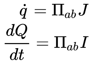
An equation that represents heat flow from material A to B is
Where Π is the Peltier Coefficient, a physical constant associated with the transition from material a to b.
TEC Structure
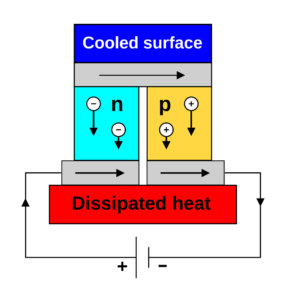
The Peltier Effect allows heat to be transferred in either direction relative to the direction of current flow, and the Peltier Effect can be approximated as a reversible process when neglecting resistive losses. TECs take advantage of the Peltier effect usually by putting n- and p-type semiconductors electrically in series, but thermally in parallel. Commonly, this material is Bismuth Telluride. The resulting device then has a heated side and cooled side depending on the polarity of current applied. In this way, TECs can be modelled as current-controlled heat pumps.
An image from Wikipedia shows a single current path (although a real TEC would be made up of many of these):
In general, a TEC is used in a system by clamping it between two plates. One plate leads to a thermal reservoir or heat exchanger, while the other plate is an interface to the target object (the object that requires temperature control). Multiple Peltier devices may be clamped in parallel to increase heat transfer capabilities. Thermal Interface Material (TIM) such as thermal pads or grease is commonly used at the interface between different components in the heat path to reduce thermal resistance.
Temperature Control
TECs are generally driven by a dedicated thermal controller that has the ability to set an output current based on a sensed temperature. If you are familiar with heater thermal controllers, TEC thermal controllers are very similar and share a lot of the same hardware except they allow electrical current to flow in both directions through the circuit. Thermal system control tuning is required in applications where the product must strictly follow a temperature profile.
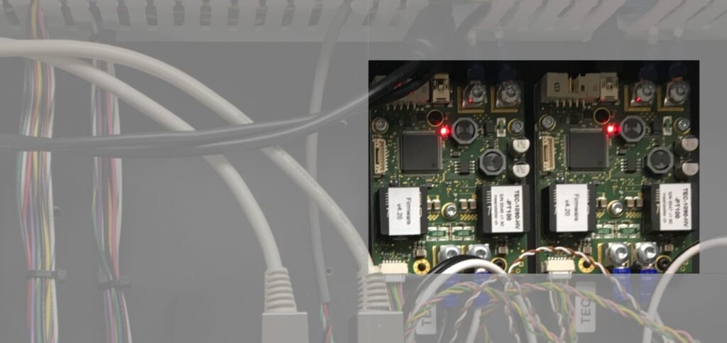
Simplexity can design custom Printed Circuit Boards, or PCBs, to serve as thermal controllers such as in the Anavasi Diagnostics Molecular Detector. In cases where a rapid development schedule is needed, Simplexity has also developed a number of products using off-the-shelf Meerstetter TEC controllers which use a Proportional-Integral-Derivative (PID) control algorithm. On two other fast-paced development projects, an array of CUI CP1130325 TECs were controlled using a Meerstetter TEC-1090-HV to control the temperature of a glass microfluidics flow cell.
In some cases, it may be beneficial to purchase a TEC system that comes with sensors, heat exchangers, and/or control electronics all together. This design path may be especially useful in space constrained systems, optimizing the heat path from the temperature sensor to TEC, or de-risking a rapid development schedule. Simplexity has engaged II-VI for these types of services in the past such as in the Library Preparation Device.
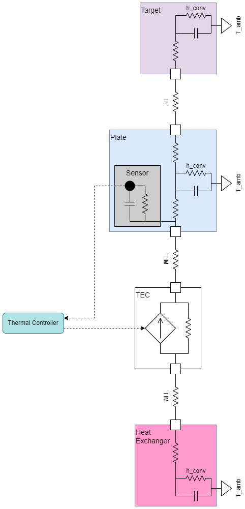
A high-level diagram showing the architecture of a representative thermal system with a TEC is shown below.
When to Use TECs
Applications that benefit from TECs are:
-
Cooling a target below ambient temperature
TECs allow you to pump heat to ambient surroundings, and they are thus capable of bringing target objects below ambient temperature. -
Rapid heat cycling
In applications that require many temperature cycles such as PCR machines, it is often desirable to reduce the overall runtime of the product. One way to accomplish this is by designing more aggressive temperature ramp profiles using the cooling capabilities of a TEC. -
Constrained Space
TECs are solid state devices which means you may avoid more complicated temperature control technologies that take up valuable real estate in your product. Although one side of the TEC is generally a dedicated heat exchanger, you can potentially avoid using pumps, tubing, and coolant in favor of a fan on heat fins. -
Precision temperature control
The inherent ability to both heat and cool targets allows you to design your thermal controller for high precision. Whereas resistive heaters can only add heat to a system, a well-tuned TEC controller can accomplish rapid temperature ramps and reduce the risk of overshoot.
Application Notes
-
Design the Thermal System, not the TEC
The responsible engineer must design the temperature control system. A TEC cannot be chosen agnostic of the surrounding heat paths. This is analogous to a motion control engineer: the engineer designs a motion system and doesn’t just pick a motor or gearbox in isolation. Although the TEC is a significant contributor to the thermal performance of a design, one must also take into account other parameters such as the thermal resistances/capacitances of the surrounding materials, convection expected at the heat exchanger, heat “leaks” along the main heat path, electrical capabilities of the thermal controller, and the maximum ambient temperature.A TEC datasheet will likely focus on two major specifications: the no-load temperature difference (both TEC sides contact perfect thermal insulators at some reference current) and the maximum heat pumped (both TEC sides contact perfect thermal conductors at some reference current). Your operating point will be somewhere between these two extremes and is predominantly a function of the surrounding thermal resistance and the drive current applied. If there are high thermal resistances immediately adjacent to the TEC, then the TEC will pump less heat and the thermal system will respond more slowly.
Note that although the system depicted above may appear relatively simple, a model that captures the relevant thermal resistances and capacitances may be fairly complex as shown below.
-
Beware of Thermal Runaway Condition
The Thermal Runaway condition occurs in cases where you are attempting to cool a target too fast or to too low a temperature. In these cases, the thermal controller pushes the thermal system beyond its capabilities and may cause damage to a product. This case is particularly likely in the early development phases when the system limits are not yet known.In addition to the Peltier Effect described above, any non-superconducting material will exhibit Joule Heating when current is passed through it. This means that no matter how well you design your thermal system, you will always be generating some heat. Let’s assume you want the thermal controller to bring the target temperature down too fast. The sensed temperature will be above the set point as the thermal system can’t keep up with its commanded temperature. Error accrues in the controller, so it tries harder to drive the temperature down by increasing electrical current. Due to Joule Heating, the temperature increases in the TEC which further heats the target and accrues more error, outputs more current and generates even more heat. Eventually, this positive feedback loop usually hits some power limit set by the thermal controller, but your design can be damaged if those limits are not yet set properly.
The risk of thermal runaway can be mitigated by careful tuning and characterization of the thermal system: explore at what ramp rate the output from the controller has a diminishing effect, and find the minimum achievable temperature using safe current levels through the TEC. The outputs from these experiments should then be used to design safeguards in your temperature controller.
-
Delays Exist in the System
Heat travelling through any material takes some finite time, which means the distance between the TEC and the temperature sensor has some associated delay. In general, delays between the sensed temperature and the controller output can cause instabilities in the system, so careful tuning must be carried out in cases where you need rapid ramp times. Moving from a PID controller to more advanced control algorithm can alleviate these issues also. Simplexity has experience designing and implementing advanced control algorithms if your system requires more performance than you are able to get from a PID controller.
Summary
TECs are widely used devices that perform well for both general and precision temperature control. They can both heat and cool targets within a relatively small package, and they can reduce the complexity of your overall system design. However, one must be careful to consider the thermal system design, controller limits, and potential instabilities before releasing a final product. With Simplexity’s careful design and analysis tools, you can take advantage of TECs with their small size, simple electronics, and cooling capabilities in your product.
Resources
- Handbook from Laird on TECs: Thermoelectric Handbook PDF
- Good top down approach for learning about different effects: Thermoelectric effect
- Linked article from Wikipedia that includes more mathematical rigor in deriving energy balances: A.11 Thermoelectric effects
- Good animations showing analogy for Peltier and Seebeck effect: Make Electricity Go Round and Round – The Thermoelectric Effect
- Example of Internal TEC design: arcTEC™ Structure – Improved Performance and Longer Life in Peltier Modules

