Sealing is challenging and important
Whether it’s a waterproof wearable electronic device, a chemical bottle, hydraulic lines in automotive brakes, or the hull of a wooden boat, sealed assemblies are ubiquitous and important in the world of engineered products. These products have sealed interfaces to keep fluids, either liquid or gas, retained or expelled from an important volume. For boats, seals keep them floating. In chemical containers, seals retain the chemical protecting the environment and the people around the container. With hydraulic brakes, the seals retain brake fluid, maintaining brake pressure. In the case of wearable electronics, seals keep water and in particular sweat out of the assembly and off the electronics inside, preventing the electronics from corroding, shorting, and then failing. In each of these cases, seals are critical to the function of the device. At the same time, seals can present a difficult challenge to the mechanical engineers tasked with designing these products.

The task of joining two parts together in a way that there is no way for thin fluids like water or air to pass between the parts can be tricky. Fluids can press through the smallest gaps, and they can move in any direction, turning even the tightest corners. Even small pressures applied to fluids can create large forces on components distorting them, and distortions can break seals.
Despite the challenges in sealing, seals often don’t receive the required analysis in the design phase. I have often felt that the proper design of seals is under-discussed among engineers. As a result, I’ve put together my thoughts on how to design a successful seal.
The first two sections below discuss the two core concepts of how to achieve a seal. The first is to establish a line through which fluid shouldn’t pass. The second is to establish margin in the seal by adding extra distortion or compression to the seal. After that, this blog will discuss some implications of those key concepts, specifically that soft materials aren’t required for sealing, why double “redundant” seals don’t usually seal better, and why corners are particularly challenging to seal. The last section has some very practical considerations, like how and when to apply the apparent magic of form-in-place gaskets, the trick of designing self-energizing, and finally a discussion of processes for evaluating seals.
Key Concept 1: Envision a Line
The first job of the seal designer is to locate the seal. Usually, several rigid components come together with an elastomer in between. For an effective seal, the designer must establish the line between the two rigid parts which halts the fluid. If this line has any gaps in it, the seal won’t seal. While it may seem trivial, gaps in the sealing line are common in first-generation prototypes. These gaps are designed-in leaks. Every place the designer has to pick up their pencil to trace the seal path is a point of potential ingress of fluid. Once that line is established, the seal designer needs to engineer the deflection in the seal to ensure no fluid can get past.
That is the first important takeaway: the seal must occur on a continuous line.
Key Concept 2: Seals need Deflection
Numerous factors can break seal path, and the designer compensates these factors with seal deflection. Whether it’s a paper gasket, an o-ring, or a wax ring for a toilet, seals deflect to fill voids and ensure there are no breaks in the seal path. The main effort in seal design is to estimate the amount of deflection required by the seal, and figure out a seal design that provides that amount of deflection.
The factors which oppose sealing are uncertainty in the final shapes of components. This uncertainty leads to gaps in the seal line. Uncertainty in final part shape can arise from tolerances, warp, load-based distortion, pressure-based distortion, surface roughness, dings, and thermal expansion. The job of a seal is to compensate for these uncertainties and close the seal path.
However, designers can usually estimate each of these uncertainties. The designer generally chooses or looks up tolerances of components. Then finite element analysis or manual techniques can be used to estimate the deflection of the components due to sealing forces, pressure loads, and external loads. These deflections often work to separate the seal. Finally, the designer must account for surface roughness, dings or other surface flaws the seal must accommodate, and any effects thermal expansion has on the parts. All these factors affect the seal material itself as well as the mating components.
With each of these factors added up, the designer chooses or designs a seal which, when installed, will deflect more than the sum of these factors. That way, if all of them happen occur at the same location and all of them pull the mating components apart, the seal will rebound and maintain contact without gaps.
However, the designer must also account for over compression of the seal. After all, many of the factors which can work to reduce deflection of the seal can also work to increase deflection. The seal design and material must be able to comply with the maximum amount of compression possible without experiencing excessive forces or distortions, and the designer should account for these as well.
The design engineer must do these calculations. It can be tempting, especially with o-rings, to compress them to some percentage of their nominal thickness and call it good enough. Rarely is it good enough. A 2mm thick o-ring compressed by 30% will not seal against 1mm of part warp.
Most of the time, careful analysis of seal deflection isn’t necessary; rather, the designer can force the seal. It’s much like designing a part for strength. When most engineers design a part for strength they estimate loads, calculate stresses, and apply a factor of safety to the design for margin. When possible, the efficient engineer moves quickly through the load calculations and applies a large factor of safety. In the same way, seals can be designed with margin. The way to design seals with margin is to have extra seal deflection beyond what is required in the analysis. That way, if parts distort too much or the system is over-pressurized, or overloaded, the seal remains intact.
That is the second important take-away: sealing margin comes from excess deflection
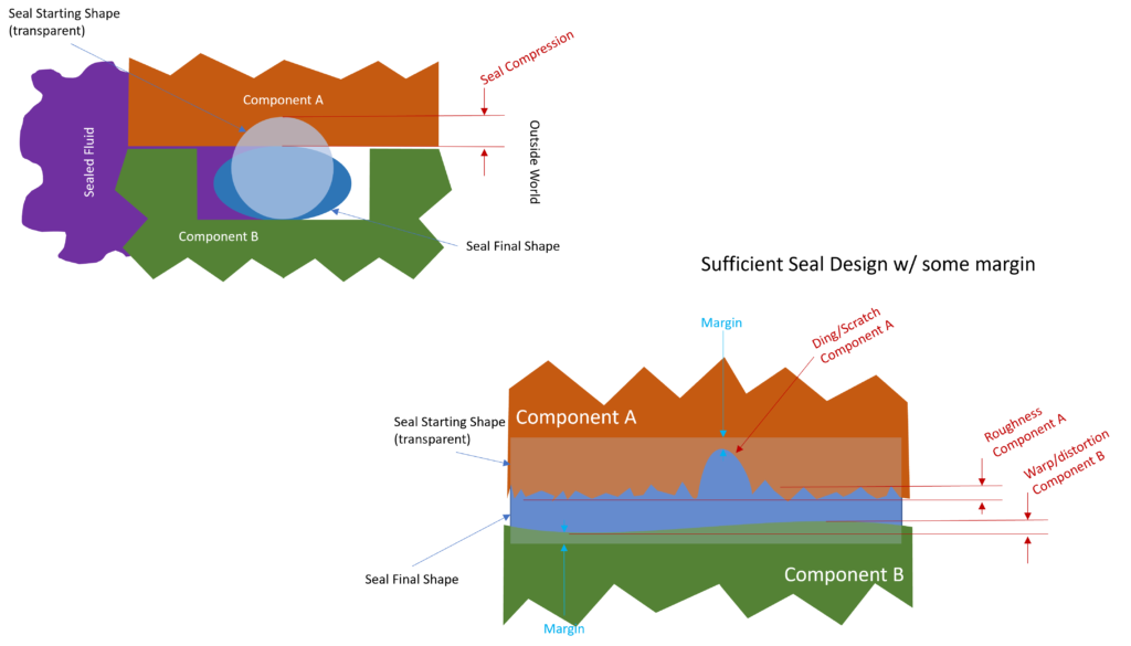
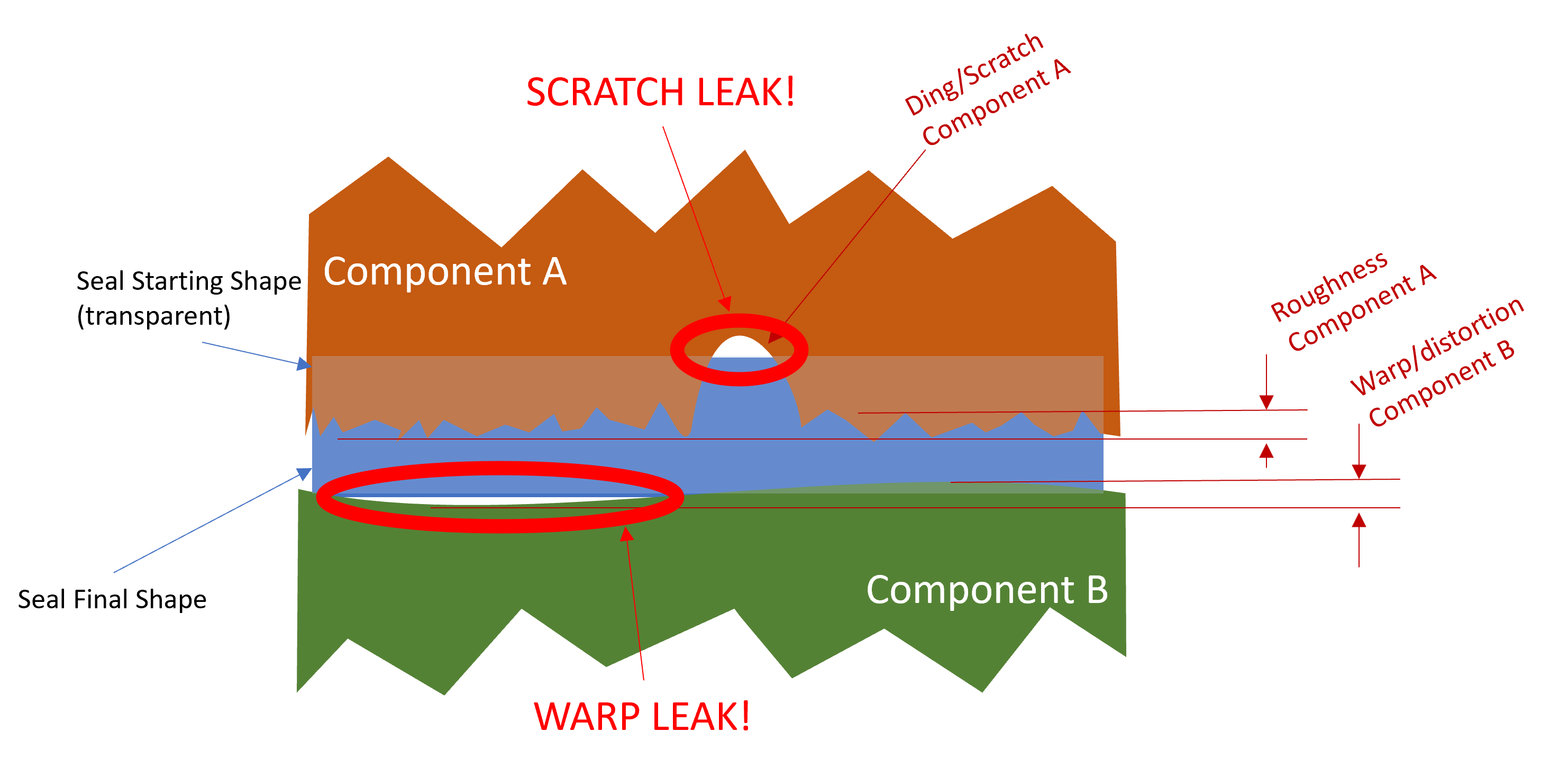
Seal deflection can take many forms. With an o-ring, gasket, or weather-stripping, it is literally the amount the seal is compressed. But other types of seals feature mechanical flexibility to achieve a seal. In fact, sealing can be achieved with rigid and hard materials.
Implication: Soft doesn’t mean sealed (but it sure helps)
It can be tempting to think “well I put an o-ring in there, so it’s sealed” or “the rubber makes it seal” but in truth, soft doesn’t mean sealed, there’s a lot more to it. In fact, there are many examples of sealing surfaces which aren’t soft.
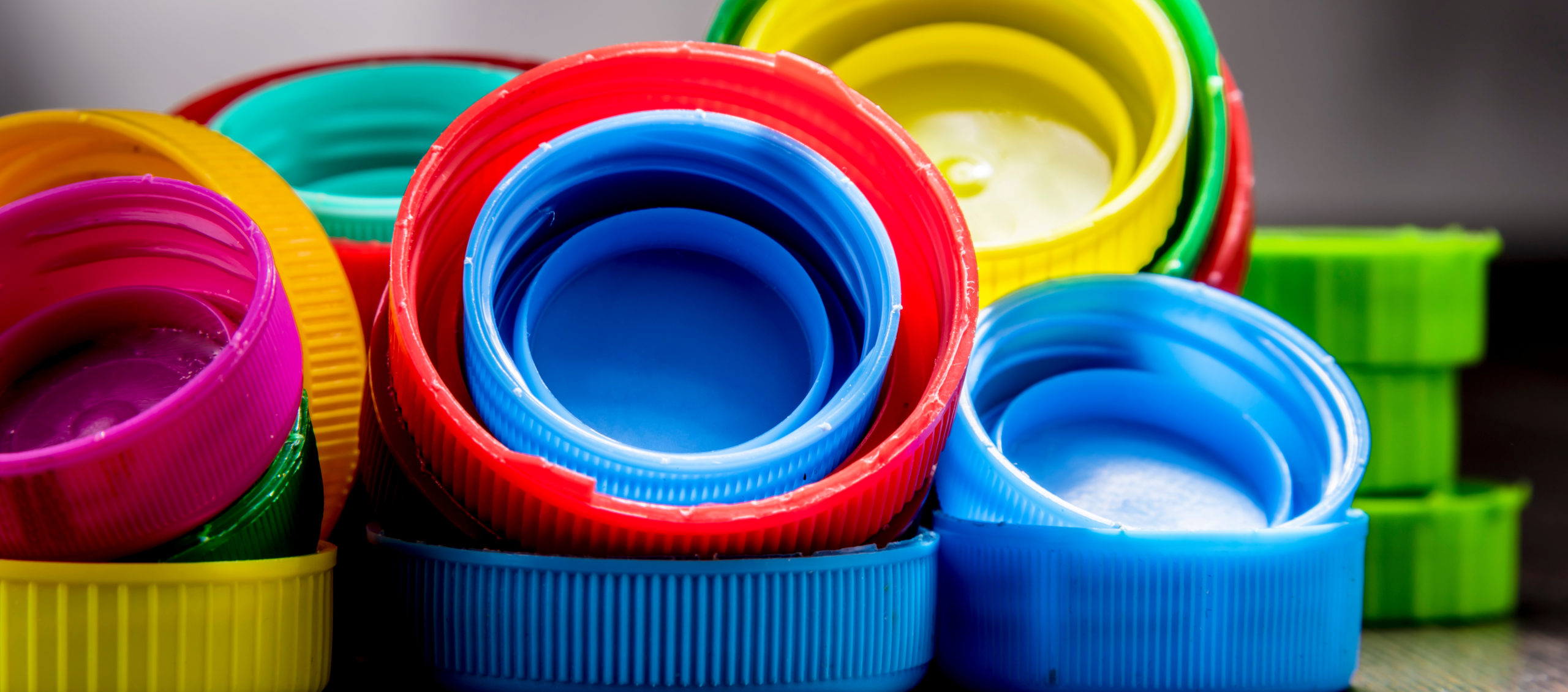
- Crab-claw seals for beverage bottles are seals between two hard plastics (usually PET and PP)
- Flared fittings in automotive brake lines and other hydraulic lines create seals between two metal components
- Multi-layer steel (commonly called MLS) head-gaskets are now commonly used in automotive engines. They are steel gaskets that seal together two large aluminum castings: the head and the block.
My favorite, however, is the cocktail shaker which seals steel-on-steel or steel-on-glass.
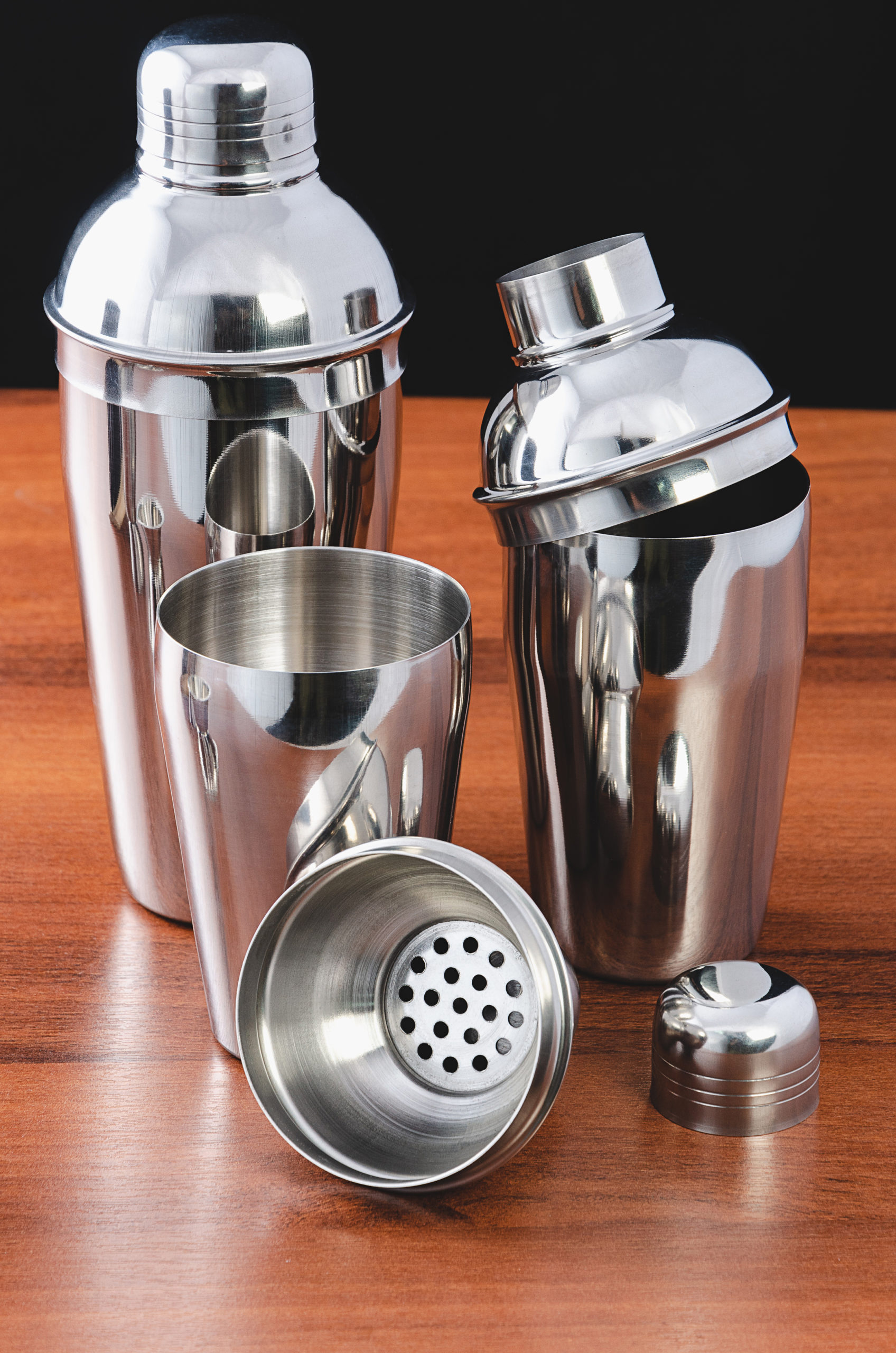
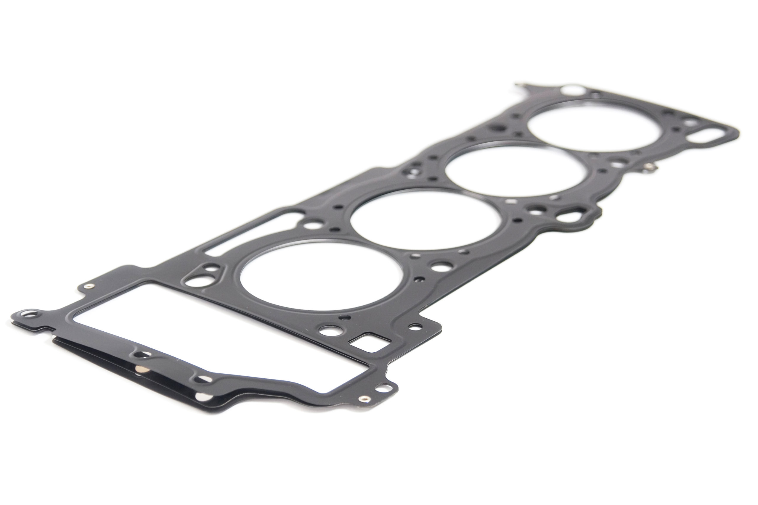
In each of these examples, tight seals are achieved without soft materials. These seals work by deflecting along a continuous line contact. They gain their compliance like a spring through the shape of the parts rather than through the material.
These seals can be challenging to work out, however, because they rely on smoothness of the surfaces in contact. The deflection of hard seals generally cannot follow little ripples, dings and scratches nearly as well as a soft material.
Also notice that most of these examples (with the exception of the MLS head gasket) are sealing a circular seal path, and they’re doing it with radial forces. The circular path with radial forces ensures even preload forces all the way around the sealing interface. If you tried to make an oval cocktail shaker, it would be extremely liable to leak on the flat sides, where there is less compression force.
These hard seals gain other advantages though. The cocktail shaker is easier to clean and longer lasting because it has no elastomer. The head gasket withstands high temperatures and extremely high pressures. The beverage seal has the advantage of requiring no additional components. Brake lines don’t expose harsh brake fluid to elastomers.
There is an important lesson in hard-material seals for the designers of soft-material seals. Compliance is key when forming your closed loop of continuous contact. For this reason, many soft-material seals also have compliant shapes. Bulb seals feature a hollow space inside to increase their compliance. Refrigerator seals have an accordion- or bellows-shaped section. Even O-rings are round in cross section because that increases compliance.
Implication: Large seal area and redundant seals aren’t better
There are two seal designs which are common but require extra attention to make functional. In fact, many times these seals really don’t work well at all. These are redundant seals and, and seals with large “seal area.”
Some seal designers will talk about seal area, and work to maximize the area of the seal. In general, though, this is not the right way to think about sealing. Large seal areas require a lot of force to ensure compression over the whole area. The loop of contact tends to wander through the seal area, and break as it wanders. The only true advantage large seal areas have is when pressures are high, and gaskets are weak, large width of the seal path can add strength or reduce undesirable seal deflections.
Another seal design which is often improperly implemented is double or redundant seals. It would seem that if one seal path is good, two is better. Also, it seems that you can make the loop redundant, then if one loop fails, the other can pick up the slack. Both of these are understandable misconceptions. The truth is that double seals aren’t really redundant because the two seals almost always interact with each other in destructive ways. There are two ways redundant seals interact, first by sharing compression forces and second by potentially trapping and pressurizing fluid between the seals.
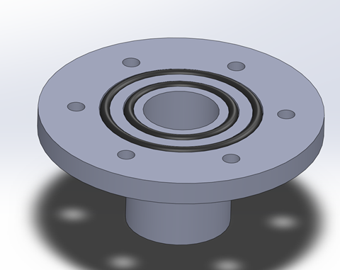
Redundant seals introduce a new sealed volume between the seals. What is the pressure in that space? It’s tempting to think that the pressure in the space between the seals is half the pressure the seals contain. But it can’t be. For the pressure between the two seals to be dependent on the pressure they contain, the inner seal must fail, allowing fluid to pass through. If the outer seal is still holding strong, and the inner seal has failed, the pressure between the seals is the same as the contained pressure. The only way for two seals to equally share the load is if both have equally sized leak areas. If they both have leak areas, they both have failed, and the design is behaving as a labyrinth and not as a seal. The pressure between the seals generally doesn’t depend on the pressure they contain.
If the fluid in the space between the seals becomes pressurized, it can unload the compression force on the seals reducing their margin. As pressure in that space further increases it can burst through one of the two seals. Pressure increases in the space between seals are readily possible. The space between the seals is usually small and subject to large percentage changes in its volume due to heating and cooling or flexing of components. In fact, usually seals can shift laterally in response to pressure or motion. If the pressure in that space is high enough to burst through one of the seals, then the advantages of redundancy are lost. In fact, the remaining seal will have less margin than if the failed seal were removed completely.
Double seals are also not truly redundant because they often share clamping forces. As the two seals share clamping force, double seals require double the clamping force to achieve the same compression. A single seal with double the clamping force will usually offer far more compression distance, leading to more margin. If the engineer establishes margin with compression distance, two seals don’t offer more margin than one, as one failed seal will still bear compression force, but reduce the compression on the remaining seal.
The argument I present above about double seals takes a very digital view of sealing, as if seals are either working or not working. Reality is much more nuanced. Designs with double seals might make perfect sense, and if properly tested can absolutely work in many applications. Many engineers have applied redundant double seals with great success. Morton-Thiokol famously applied double o-ring seals for NASA in the design of the Space Shuttle’s solid rocket boosters. While that seal famously failed, causing the Challenger disaster, my opinion is that the failure was due to an organizational failure, and had nothing to do with the engineering, least of all because double o-rings were used.
Implication: Corners are especially challenging
One of the most likely places to have a leak in a complex design is where three or more parts come together. These areas are likely to leak for several reasons. The joint of 3 components first makes design of the closed loop of continuous contact more difficult because the loop must split. Second, achieving compression at the corner can also be challenging. Finally, often the external corners of parts are difficult to control for contour and sharpness, usually leading to a hole.
The first problem is achieving the line of continuous contact between three parts. The design must include a method for this line to split into 2 lines. It can be tempting to seal, for example, component A to component B, and then the pair of them to component C. However, often designers forget that the seal between component A and B must also seal to component C and leave a designed-in leak path. The solution is usually to create a T or Y shaped seal so that a single sealing material connects all three parts, however this design also has challenges.
Three-component corners also create challenges in achieving compression. The diagrams help elucidate these challenges. If component B first compresses the seal against component A, it will resist sliding down to compress the seal against component C. The same problem occurs if the process is reversed. The best compromise is to compress the seals simultaneously by sliding component B in diagonally, however this process means that both seals are distorted diagonally, and it can be difficult to implement in a practical sense. Challenges with compression and with establishing the sealing line are augmented by imperfect components.

Most components have exaggerated imperfections at the corners. With tight, sharp corners, the corner is susceptible to damage making it fit poorly. Sharp corners also add risk of damage to sealing elastomers. Radiused corners are also problematic at three-component interactions because they increase the space the sealing material must fill, and radiused corners can be difficult to manufacture consistently and inspect for shape.
In general, designers should use caution when designing 3-part interactions. A bit of creativity in the part design process can often avoid 3-part corners. Where the designer can’t find a way to avoid 3-part corners, they should design the interaction very carefully. Sometimes though, a dab of RTV is enough to cure corner woes.
Form-in-place magic and mythology
Form-in-place gaskets, RTV silicone, and curing liquid sealants present an extremely effective means of sealing, but they have notable drawbacks. The effectiveness of form-in-place gaskets has made them ubiquitous in automotive sealing for good reason. They are effective because of their high initial compliance and their ability to handle tensile forces. Form-in-place gaskets are, however, challenging in production and service.
Form-in-place gaskets are what industry calls RTV and other elastomeric adhesives, or what we in the office call “goobie.” These are sealants which are not as strong as adhesives but do stick to surfaces. They start as thick or thin liquids and cure (usually with exposure to humidity in the air but sometimes with UV light) into soft rubbers. The cured rubber fills the gap between two parts, and gently bonds them together. Form-in-place seals are special for several reasons. First, they require almost no compression force to deflect the liquid to the right shape. As a result, there is little to no distortion occurring from clamping forces. Second, the gasket that is formed is shaped exactly to the gap between the particular parts to which it mates. The gasket compensates for tolerances and surface imperfections that way. Finally, the form-in-place gasket also sticks to both parts. The adhesion combined with the cured rubber’s elasticity mean that the gasket can stay connected to both parts as the parts distort with pressure, loads, and temperature changes.
Of course, “goobie” has its drawbacks beyond the fact that it can’t be used for a sliding or dynamic seal. Form-in-place gaskets are challenging from a process development standpoint and from a serviceability standpoint.
On the process side, the act of laying down a bead of thixotropic goo which is the right height and width, has the right amount of adhesive per inch, and in the correct location is very challenging. Furthermore, the uncured adhesive can be scraped away or distorted by the rigid parts as they come together. As a result, the assembly-to-assembly variation on this process will always be high. When applying form-in-place gasketing, design engineers generally hope that the form-in-place properties of the gasket will outweigh the part-to-part variation.
Variation with form-in-place gaskets is particularly bad if it is performed as a manual process. To reduce variation, many manufacturers choose liquid-dispensed adhesive machines. These are typically 2 or 3 axis gantries that are computer controlled and dispense sealants or adhesives. While these machines can be quite consistent, they will never be as consistent as a molded rubber gasket or a die-cut sheet.
Because of the high process variation, design engineers should work carefully on the shape of the joint where they want to apply a form-in-place gasket to ensure the design is tolerant of different amounts and shapes of applied adhesive beads.
The other key disadvantage of “goobie” is in serviceability. The serviceability on form-in-place gaskets is really challenging. First of all, RTV and other form-in-place materials are weak and adhere poorly to surfaces, so it is generally possible to dis-assemble a form-in-place gasketed joint, but the problem is in re-assembly. The gasket material will be stuck to both surfaces and will require meticulous scraping to remove. Also, old sealing material must be removed before a new seal is made for good performance. Surfaces must then be cleaned and degreased for good adhesion of the new form-in-place gasket material. I genuinely believe that mechanics and technicians around the world despise engineers who specify RTV on any serviceable seal.
Self-energizing seals
Perhaps my favorite type of seal design is the self-energizing seal. These seals contain pressure or vacuum effectively without high compression forces. The trick with these seals is that they use the actual pressure applied to increase the effective compression of the seal.
Self-energizing seals have a hollow space exposed to the high-pressure side of the seal. As pressure is applied to the assembly, it fills the hollow space and tries to expand the seal, reinforcing it, and adding margin. The higher the pressure, the greater the seal margin until something breaks.
One of the most common applications is cup seals for shafts. Of course, these seals only seal pressure in one direction.
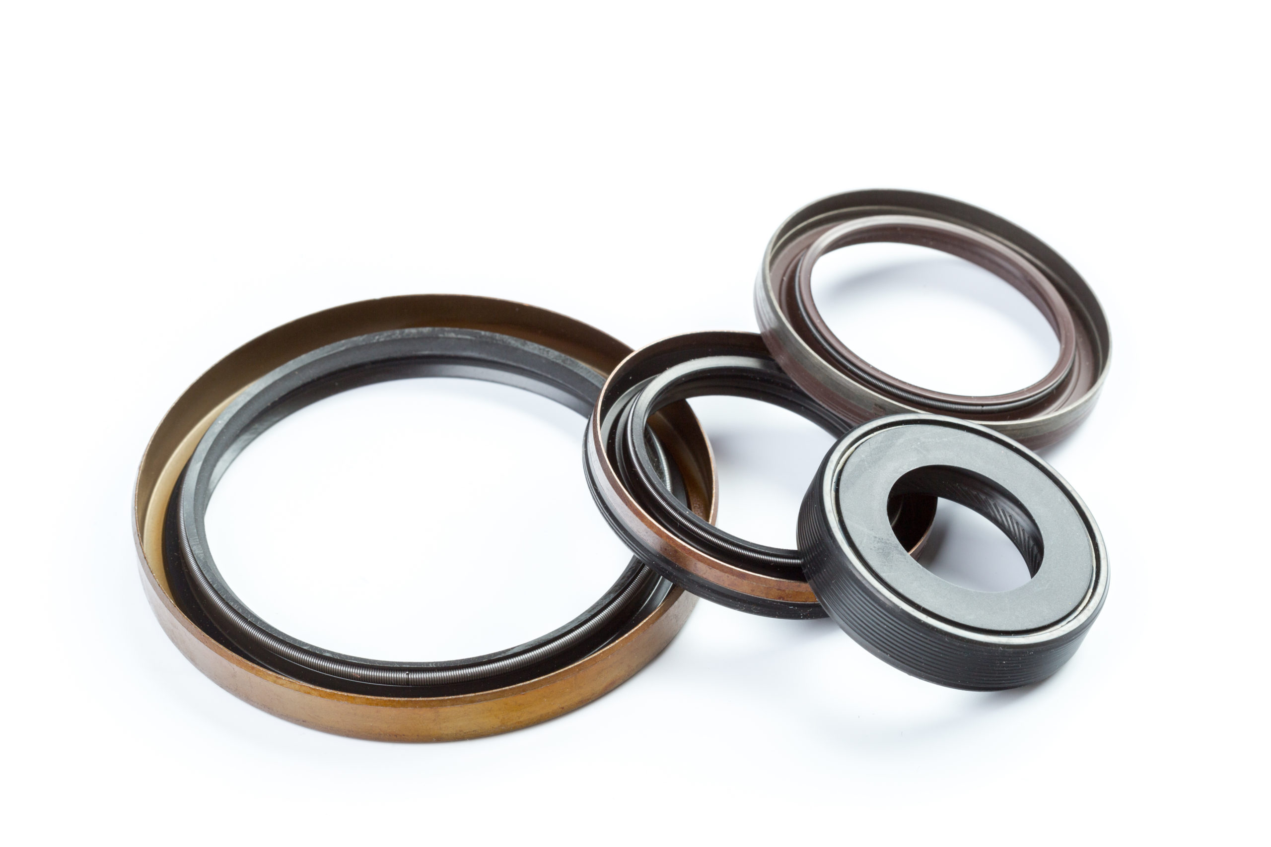
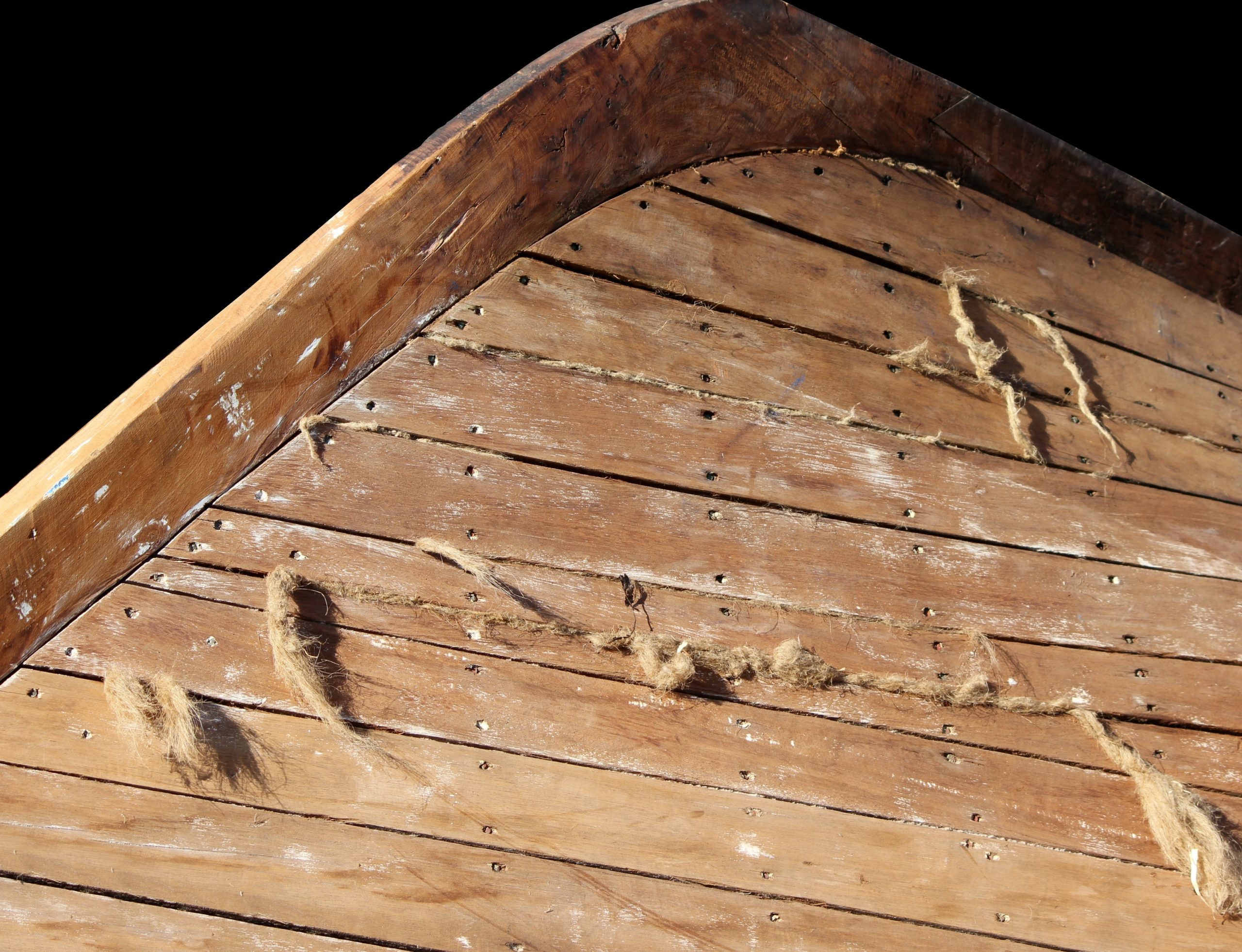
Pressure-activated seals are the most common type of self-energizing seal, and what is typically meant by self-energizing. However, there are other ways to have seals self-energize that aren’t pressure dependent. Historic wooden boats have a unique means of self-energizing.
Wooden boats require a lot of seals. In planked construction each plank must seal to its neighbors. The seal is achieved by caulking, also sometimes called corking these seams. Caulking is traditionally done with cotton yarn packed into the seams followed up with a paste-like material called paying compound. When the boat gets wet, the wood and the cotton swell up, further compressing the seams, keeping water out. In fact, many wooden boats leak the most when they are first launched, only to seal up after the planks and cotton absorb enough water to swell.
Evaluation and finding leaks
Methods of evaluating seal performance may be even more important than the design of the seal. Without methods of testing a seal, the design engineer will never know whether the seal works. Several methods are popular for evaluating seal performance including drip testing, pressure drop testing, and bubble testing.
Drip testing is perhaps the most basic means of evaluating seals. This method finds utility only with liquid seals, typically in tanks or containers. All the method involves is filling a container with liquid and looking for drips, usually after a certain amount of time has passed. This method faces a problem in that a “no drips” result doesn’t tell the tester if the seal has lots of margin or barely any. Methods for “stressing” the seal can help establish margin. Pressurizing the tank can stress a seal by forcing liquid against it. This technique can prove problematic though. If excess pressure is well beyond design pressures for the components, they can distort an unrealistic amount, forcing a leak. Also, if any of the seals are self-energizing or behaving as if they are self-energizing, excess pressure can make a seal less likely to leak.
Another way to stress a seal for drip testing is to artificially reduce its compression. For example, imagine a bolted connection sealed with an o-ring. If the joint seals successfully with half the bolts partially tightened, then it likely seals with margin using all the bolts fully torqued.
Many engineers also select pressure drop testing to measure the quality of seals. In this process the seal is pressurized, typically with air, and the pressure is monitored over some period of time. Finally, the tester calculates the pressure drop over the time period. Advantages of this method include that it makes little or no mess if done with air and uses readily available instruments and equipment. This method also has its pitfalls.
To interpret pressure drop test results, the tester must understand the implications and limitations of the test. First, a leak rate evaluation must be done at a realistic pressure. Some seals or joins can seal better at high pressures or better at low pressures. Second, the drop in pressure will depend not just on the quality of the seal, but also on the compressibility of the enclosed volume. Small pressure drops could just be because it’s connected to a large volume of air. Larger pressure drops are typical when incompressible fluids like water or oil fill the container. If the rigidity of the container or the compressibility of the contents changes, the pressure drop will also change, even if the leak rate remains the same. Finally, temperature changes can impact the results of this kind of test. The pressure readings may be due only to changes in temperature.
Another popular method for detecting leaks is with bubble testing. A sealed assembly is pressurized with air and submerged in a liquid, usually water. Where bubbles come out, it leaks. This method is powerful for debugging and finding leaks. However, bubbles may not always be visible or may be trapped or hidden by features in the assembly.
Regardless of the sealing requirements, type of seal, or seal design, seal tests are necessary in the development of a sealed system.
In Parting
Many designers are intimidated by seal design, and all mechanics and technicians have experienced leaking seals at some point. At the same time, seal design is required in many applications. Seal design needn’t be intimidating to mechanical engineers though. With a clear seal path and adequate deflection, parts can be reliably sealed together.
Fast Tips:
- Envision the line no liquid will cross.
- Calculate required deflection. Add excess deflection. Sealing margin comes from excess deflection.
- Give it space. Big seals are always going to be easier.
- Tread carefully among large seal areas and redundant seals.
- Avoid three-part interactions in the design.
- Evaluate your sealing performance.
- Self-Energize if possible.
- Form-in-place gaskets can really work well if the application process is controlled, and service is rarely required.
- Finally, sealing is a regular engineering problem. There’s no magic to it.


