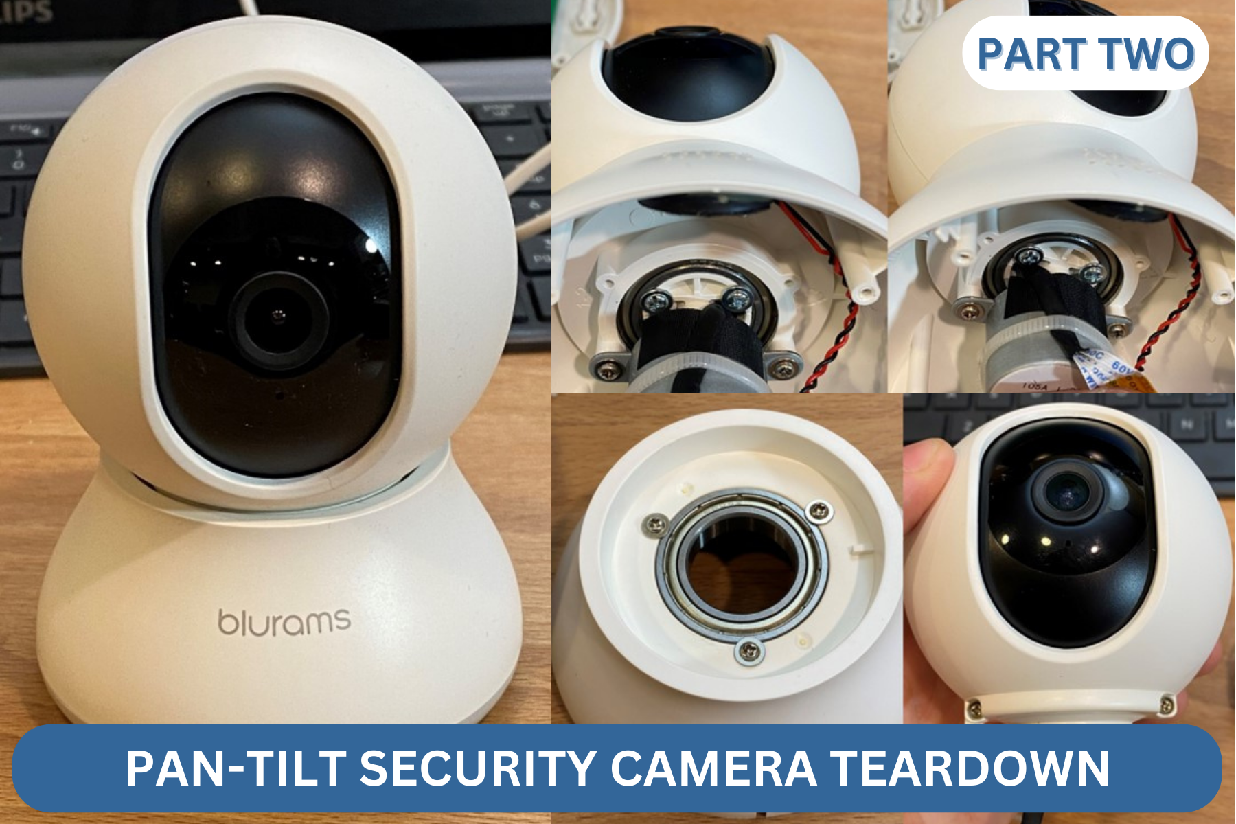
Welcome back to the product tear-down of a Pan-tilt camera! This is part two, where we’ll open up the ball head and see what’s inside. In part one of the teardown, we had a look at the base components and the parts which make up the panning rotation axis. We took apart a stepper gearmotor drive, looked at button design, talked about light pipes and examined fasteners and some plastic molding details. In this next part we’ll crack open the ball-head of this camera, look at the camera and lens assembly itself, look at the tilt axis and discuss more about molding plastics and plastic selection.
As in part one, there will be lots of pictures. The pictures come in order of disassembly, and below each picture I’ll discuss what I see in the design of the product.
We’ll start by turning the two screws which hold the ball-head together to the left.
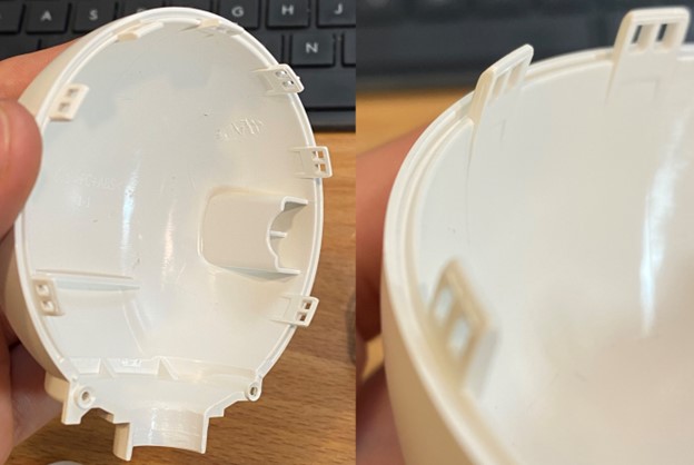
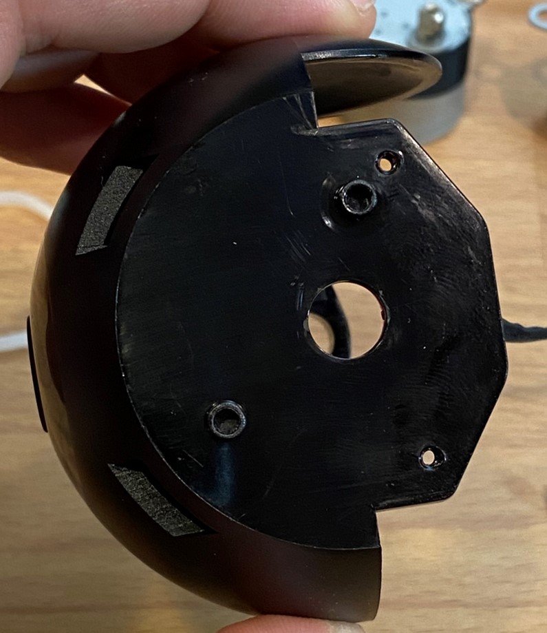
In addition to the two screws, the ball head is held together with seven snaps all around the edges. These snaps are an important feature. While tolerances of plastic parts are good, the human eye is uncompromising about seams and gaps where case parts come together. Use of many snaps all around the perimeter as well as a tongue-and-groove joint at the edge helps the fit look correct and even. Each of the plastic parts deflects to match the other in shape. That way the edges of the parts meet nicely and make for a clean looking joint between the parts. The particular snaps in this design are dis-assembly resistant, or one-time assembly snaps. The hooks have a tapered lead-in surface to assist in assembly, and a steeply angled face resisting dis-assembly. Despite this I was still able to pry the ball head apart.
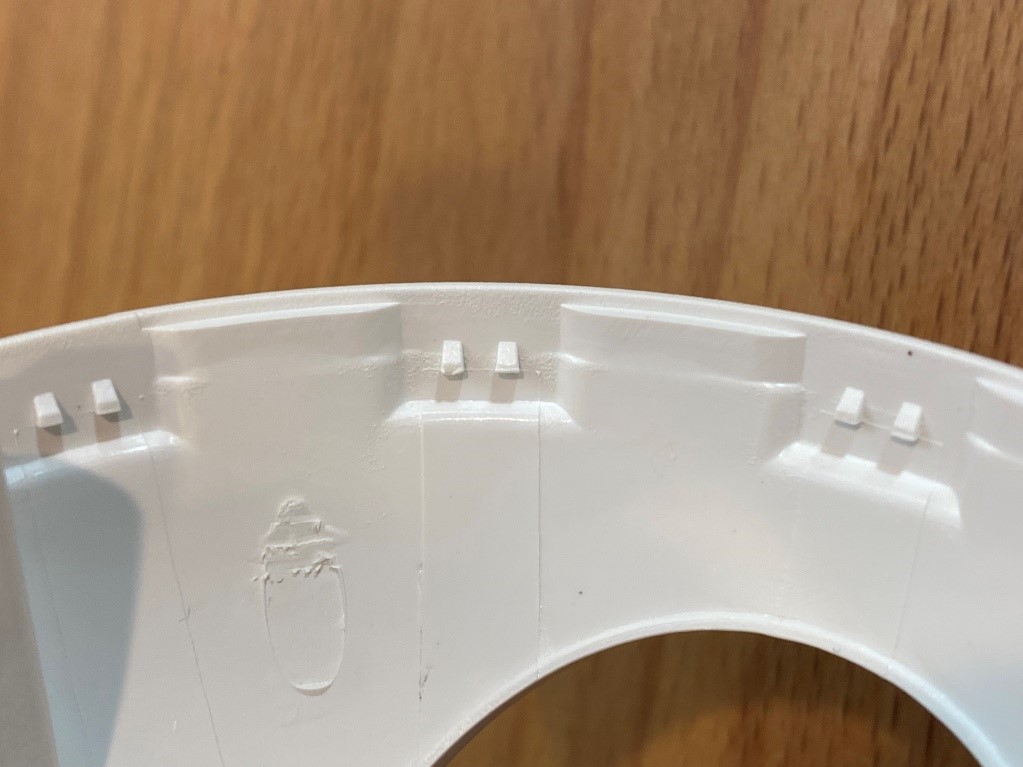
I want to draw attention to one molding defect. In the bottom picture there is a wrinkly area at the top of an oval mark. This is the mark of an ejector pin, used to push the part off the core of the mold. The ejector pin is required there, close to the side, but the surface it is pushing on is quite steeply sloped. When the part is ready to be ejected, it is still hot and soft. That ejector pin is trying to push on a steeply sloped surface slips a little and rolls up the plastic on the surface. Grid-textured ejector pin tips help alleviate this issue and are used in the base part. It’s possible these ejector pins were added to the mold to solve a problem after the tool was initially built. In truth the small surface defect on the interior of the part is unimportant.
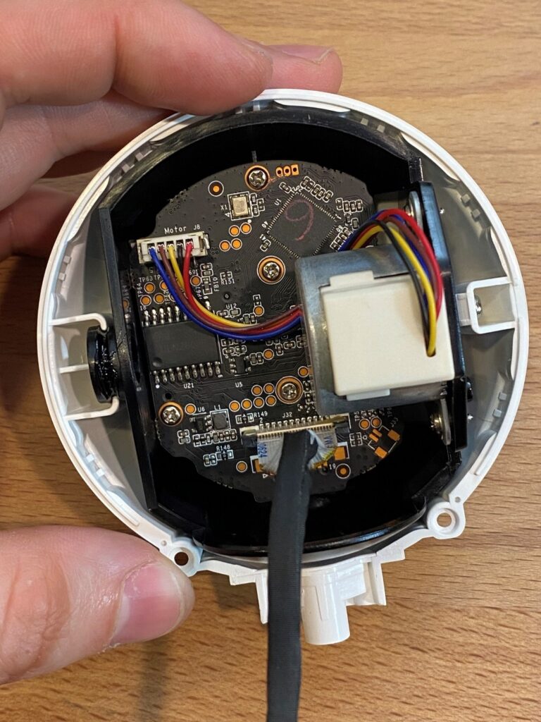
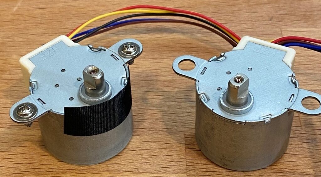
The ball head contains a black cradle component which supports the main circuit board, tilt motor, and camera. The cradle is held with a plastic bearing on the left and with the motor bearing on the right. This is the same motor as is used for pan axis. This application is a reminder that either the shaft or the body of a motor can be fixed. Generally, the body of a motor is fixed and the shaft spins. However, in this gimbal, the motor shaft is fixed and the body of the motor spins.
The bearing surface on the left features no specialized plastics. There’s some grease on this bearing surface. Grease here lowers friction and reduces wear, but I suspect the grease’s primary purpose is to reduce noise.
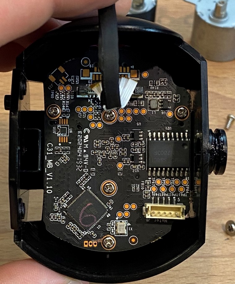
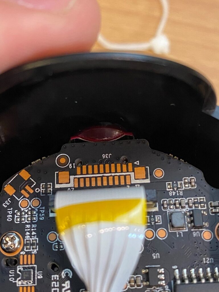
The same black-wrapped, bundled, flat-flex cable seen in the bottom part of the device extends up into the cradle. At this end of the cable, it is attached to the board in a connector. However, there are no strain-relief features at this end. As a result, the cable will pull and bend at the connector. This flat flex will only have a limited amount of life at this joint. Presumably the designers of this device tested the number of cycles and found it acceptable.
Also note the use of a matte black solder-mask on the circuit board. The solder mask is the main area of the board where there are no electrical components. Solder masks are traditionally the green color typical of circuit boards, but black, blue, red, and purple are also available. In optical applications where there’s a chance that stray light may come in, it’s good practice to use black. This reduces the impact of reflected stray light. Many solder masks are glossy, but this one is matte for optics.
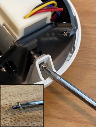
The tilt motor shaft transmits torque through a double-flat, same as the pan motor. However, to prevent the plastics from flexing so much that the motor shaft slips out of its hole, a screw is used. Axial screws like this are liable to loosen due to motor torque. Should the two flats rock back and forth or shift in the plastic over time, that rocking motion can loosen a screw. Therefore, this washer-headed screw features a bit of blue thread-locking compound to keep it tight. The driver can barely access this screw. This is because the seam between the ball halves runs through the rotation axis. Neither the split line between the parts nor the fastener can move, but crosshead drivers work at an angle, just inefficiently.
The only difference between the two motors is that the pan motor has some of the nylon cable-wrap applied to it to protect the flex cable from chafing on the can of the motor. Even the cable lengths are the same. Using the same part twice doubles the purchase volume for the manufacturer, further reducing cost.
On the side of the cradle there are two hollow pins molded into the part. These hollow pins swing around and contact a feature on the ball head and stop the rotation of the cradle. Sturdy, reliable hard stops like this at the ends of travel are usually critical in any motion control device. They ensure nothing gets broken should the device over-rotate. Hard stops also provide reference positions for the control system to find the ends of its range of travel.
With the motor removed, we can get a better look at the main circuit board and how it is attached. The three screws at the edges of the board attach the board to the plastic and the two in the middle secure the lens in place. This board also has a round hole and an oval hole which engage with two pins in the plastic. The locating pins are just below the two upper mounting screws in this picture.
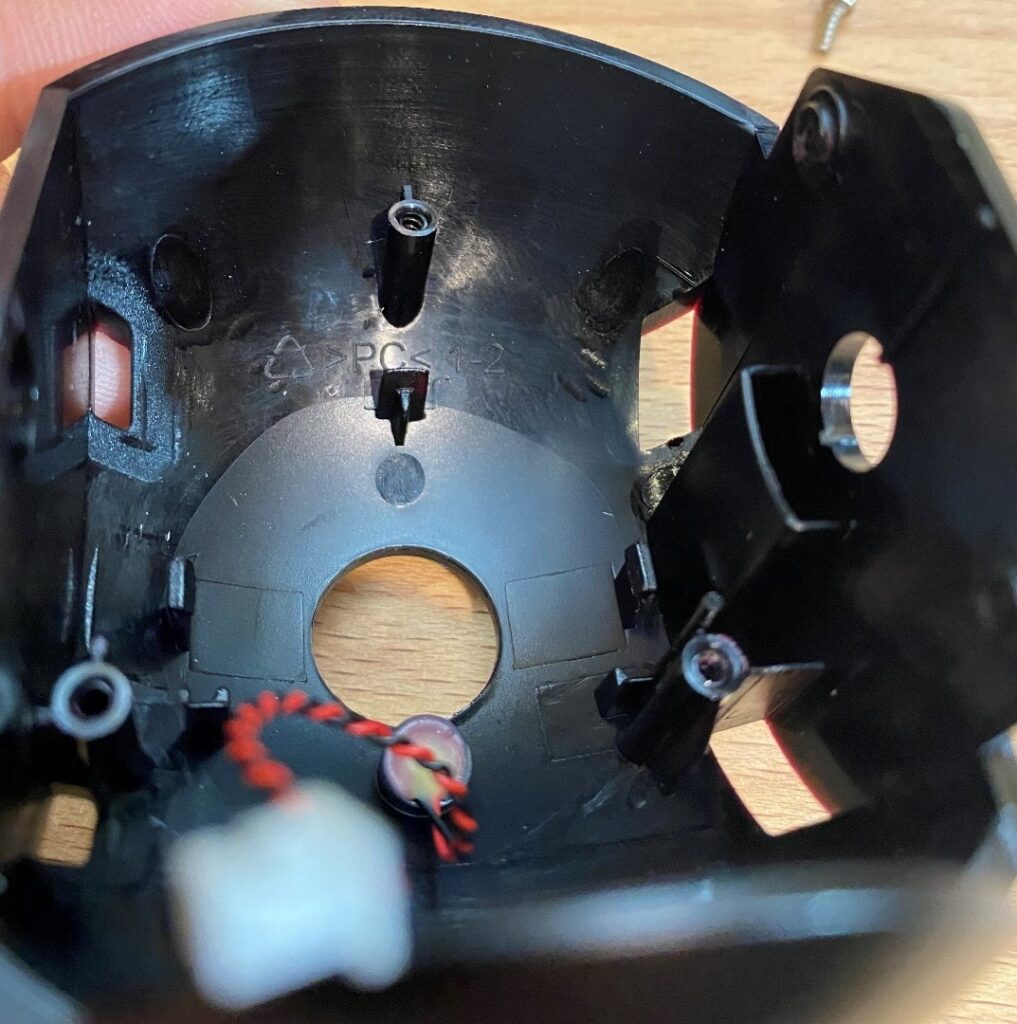
There is a micro-SD card slot on the underside of the board in this area, and a slotted feature in the plastic to allow access to the card. This card is to store recorded video. What caught my eye was the red color of the slot feature viewed from certain angles. Looking more carefully at this cradle, I saw the red color multiple places when viewing from certain angles. It turns out the cradle isn’t a black part but rather a darkly dyed transparent red part. More on this later.
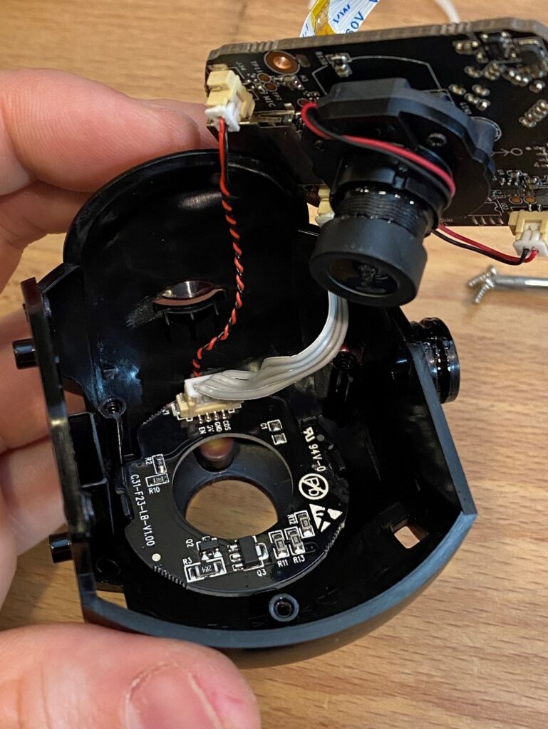
With the main board unscrewed, more features are visible. There was a surprising-to-me second circuit board there. Interestingly, this board is mounted with snaps instead of screws the way both of the other boards are mounted. It isn’t readily apparent why snaps were selected for this interface in place of screws. The snaps do add complexity to the injection mold which makes this part. That said, snaps generally reduce assembly cost. It’s also possible that these snaps are evidence of space constraints.
The large Pb marking crossed out is interesting. It indicates that this board is a lead-free assembly. Lead gives solder alloys easier processibility, and it essentially eliminates the possibility of the dreaded and difficult to diagnose tin whisker problem. The problems with lead are its toxicity and environmental harm. As a result, lead is essentially banned from consumer electronics. It seems this board is announcing its compliance with these regulations.
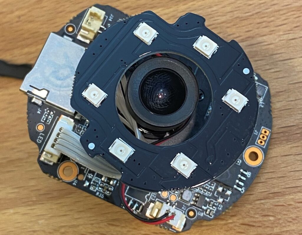
The purpose of the mystery board is given away by the marking where it connects to the main board and by the components on the hidden side. It is an LED lamp assembly. But why would LEDs shine directly into black plastic? It has to do with the “night vision” functionality of this camera. This camera can see in the dark by seeing in the near infrared. Near infrared light is different than thermal vision infrared in that it’s much closer to visible light. It essentially behaves like one color of visible light, just beyond what humans can see. This camera has a near infrared image sensor included with the visible light sensor so it can detect near infrared.
When it’s dark though, usually there’s no near infrared light as well as no visible light. So, for this camera to see in the dark it needs to create its own light. These near infrared LEDs illuminate the room in invisible light, which the camera can detect.
Remember that the cradle looks red with light shining through it? The dyes chosen for it do not block near infrared, and also fail to block some visible red light as well. As a result, the black-looking cradle is transparent to infrared light coming from the LEDs so these hidden LEDs can illuminate a room.
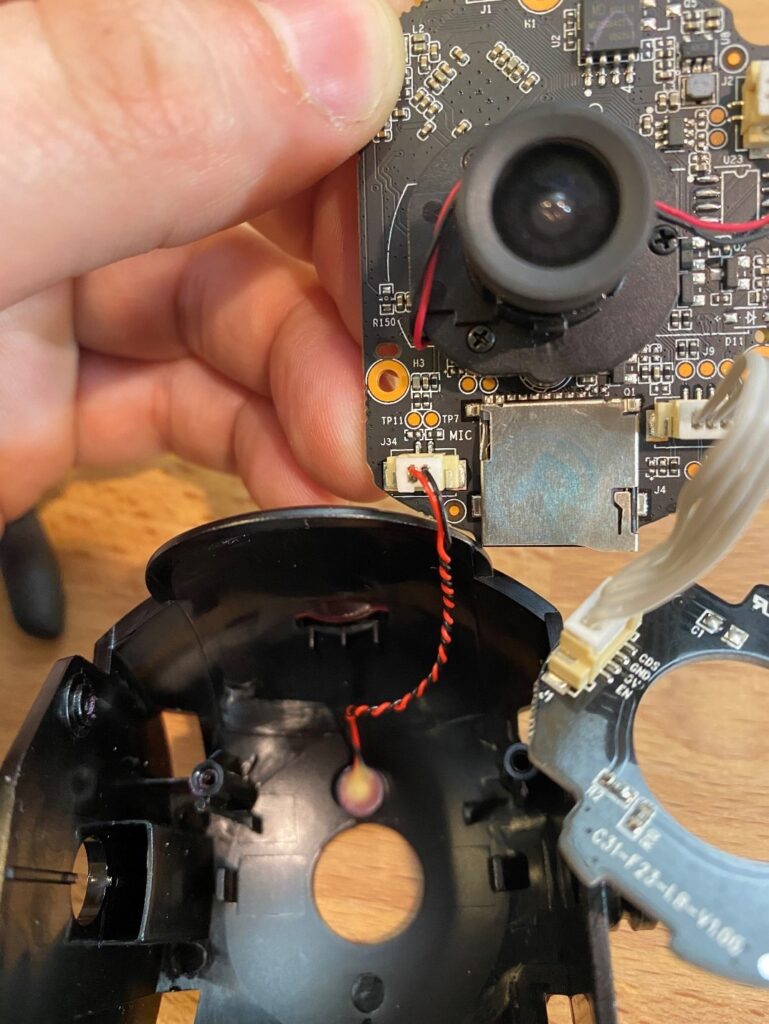
In the spirit of reading the boards: text on the main board gives away the purpose of the twisted pair of red and black wires. That’s a small microphone. Using a twisted pair on a microphone is a good idea if you can’t afford shielding for the wires. Those wires are likely to pick up electrical noise if not twisted or shielded. The most likely sound they would pick up is a 60hz hum from household wiring in the US or 50hz other places in the world. This would make for an annoying sound on any live feed or recording from this camera.
The cradle is another lovely, complex injection molded part. This time it’s labeled as PC for polycarbonate. Polycarbonate is an excellent engineering plastic for many purposes. It’s strong, tough, impact resistant, molds nicely, is reasonably priced, and is naturally clear. In this case it was likely chosen in no small part for its clarity.
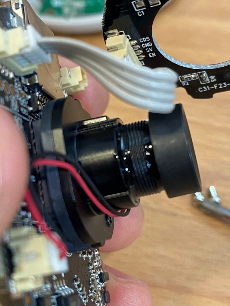
Back on the main board we can see the lens mounted directly to the board. The glossy dab of goo caught my eye. Why is there glue on the threads to the lens? The answer is tolerances, and eyes are unforgiving. Let me explain. No part is made perfectly. It’s always slightly different from the part designed. These slight errors give rise to tolerances in designs, that is how far off from the nominal the component can be. Optics have tolerances too. Lenses may have a slight error in their focal lengths, and the parts which hold the lenses also have tolerances. Eyes are uncompromising about focus. Therefore, optical assemblies almost always need an adjustment of focus at the assembly level to ensure good image quality. On inexpensive and small optics like this one, the adjustment is usually achieved with a threaded barrel, you can see the threads on this lens. At a calibration step in assembly, an operator turns the threaded barrel to adjust the focus exactly right, and then glues it in place. The glossy material on the outside of the lens is the glue there to hold the focus adjustment in place.
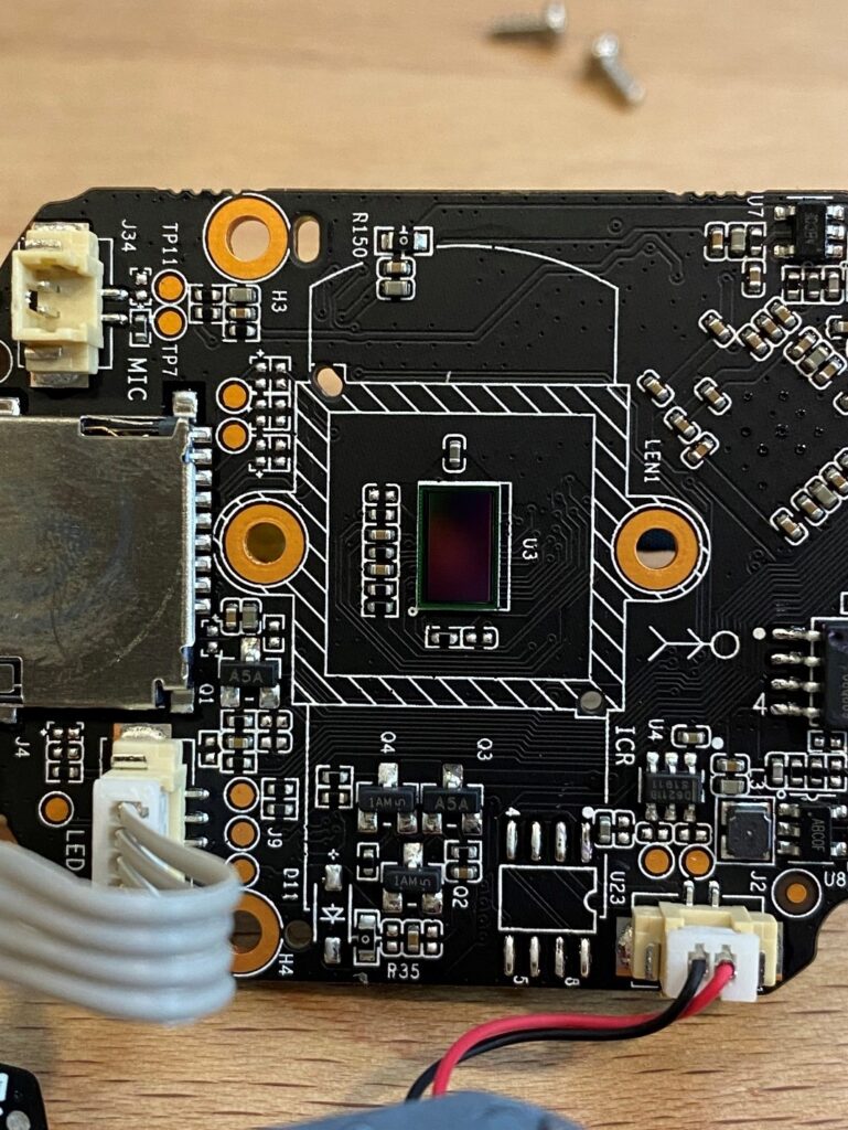
The lens comes off with two small machine screws and exposes the image sensor, labeled U3, on the circuit board. This image sensor is interesting in that it works in both visible light and NIR. On that little chip is an array of pixels. This camera is advertised as “2k resolution” meaning the sensor has a grid of about 2000 pixels width and 1000 pixels height. In reality, they’re usually 1920 × 1080 pixels. The sensor is sideways in the image above. Each of these pixels has a color filter over it that passes either red, green or blue. The different filters are patterned on the pixels so each has a neighbor with a different color. (The most basic pattern of red, green and blue pixels is called a Bayer filter, though other systems of arranging red, green, and blue pixels exist.) To make this camera work in the near infrared, these color filters are modified to allow near infrared light to pass as well, so all the pixels detect near infrared if it’s available.
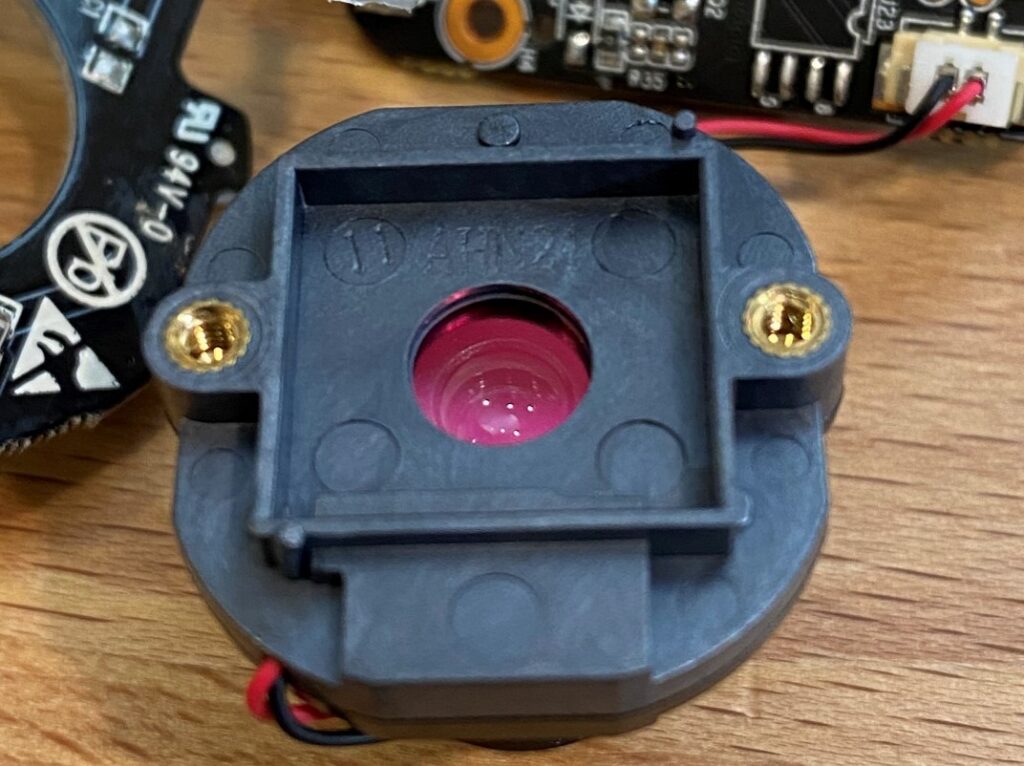
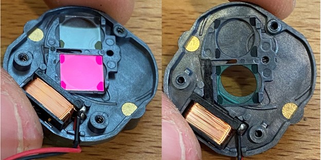
More questions arise when the lens comes off. Why does the backside of the lens look red? Why does a lens need a black-and-red wire pair coming off of it? And why does it rattle when it moves around?
There is a back plate on the lens which I removed to answer these questions.
The back plate of the lens is this assembly. There are two bits of glass in it, they are the thing that rattled in the lens. When tilted just so, it’s apparent that one of the two filters has a slightly red hue. When tilted another way, however, the same filter appears greenish. A shiny black lever extends from the coil and engages with a slot between the two filters. The lever is actuated by the solenoid in that coil of wire and swings clockwise about 90°. When it does, it rotates the filter pair around so the clear one can be in front of the camera as well as the red-or-green one.
The red-or-green looking filter glass blocks near infrared light. This is important because daylight includes a lot of near infrared light, as well as visible light. All three of the image sensor’s types of pixels (red, green and blue) all also sensitive to near infrared. That means the near infrared light will wash out the color light, making for poor color quality. The purpose of this red-or-green looking filter is to block the near infrared so that in daylight only the visible colors influence the image. Then when it gets dark, that small solenoid can flip the lever swapping filters to a clear one. The near infrared LEDs also turn on in the dark, and now the camera can see in the dark.
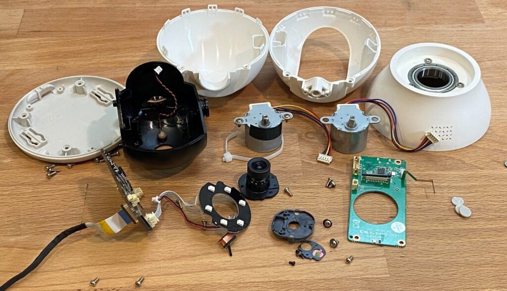
That concludes my disassembly of the pan-tilt camera. Here are all the parts laid out on my desk. I learned a lot about how this camera works and came away with some ideas worth using in my own designs. I hope you did the same.

