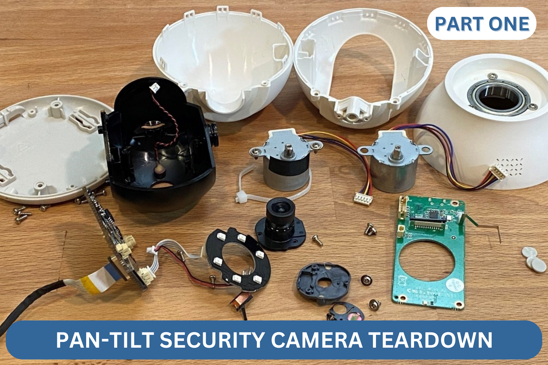
I purchased a home security camera with the intent of taking it apart and learning how it works. The camera was inexpensive and mechanically complex, featuring a two-axis gimbal, a camera, speaker, microphone, and a system for “night vision.” This is one of many security cameras on the market now which connect to WiFi and provide monitoring from an app.
This is the first part of a two-part series. In the first part we’ll look at the base of the gimbal and the mechanism that makes it pan right and left. We’ll examine construction details exposed along the way. In the second part, we’ll take apart the ball-head. There we’ll have a look at the tilt axis, as well as the camera and lens assembly.
Inside the camera I expected to find the design to be an implementation of a variety of low-cost features and techniques. This is a complex device for its price, and I wanted to see how the manufacture achieved their selling price. Before looking for screws to turn, I set it up and used it. Mechanically, I was impressed with the range of the panning motion and how quietly it moved. I was also impressed by how robust it felt. Inside the device I find answers to how it was constructed, and I learn a few things along the way.
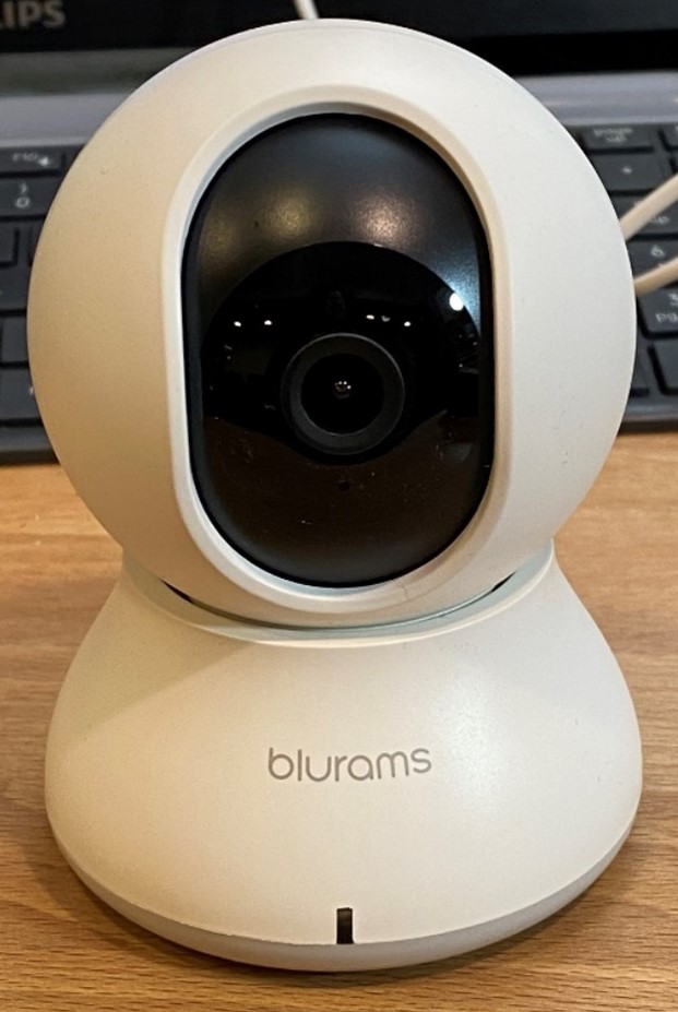
Here is the camera is sitting on my desk. Starting disassembly is often the hard part, but looking at the bottom gave it away.
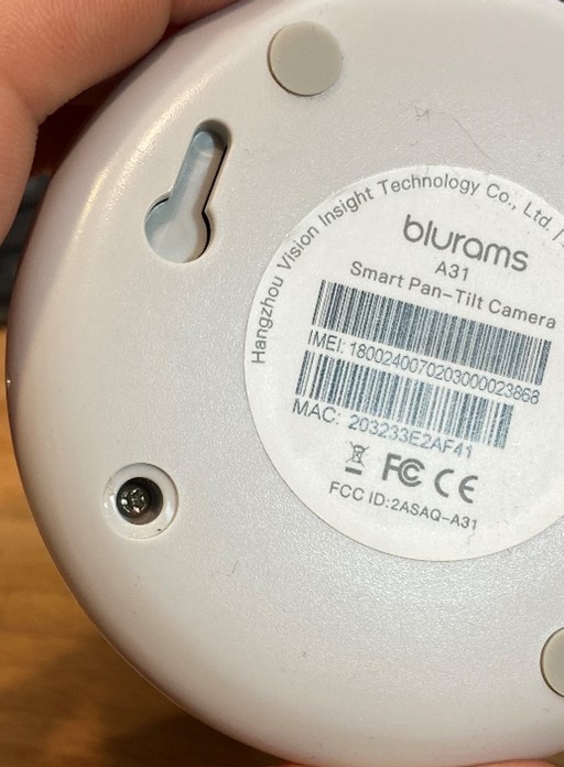
The camera features 4 little rubber pads for feet. It’s always surprising to me how much of a difference little rubber pads make for a plastic device’s stability. The additional friction of the rubber keeps it from sliding, and the slight elevation keeps it from rocking.
You can also see in the picture the keyhole mounting feature for hanging the camera on a wall. These keyholes hide a secret we’ll see soon.
As is often the case, the rubber feet hide the screws. I’ve removed one foot in the above picture already. Removing those screws allows removal of the base plate.
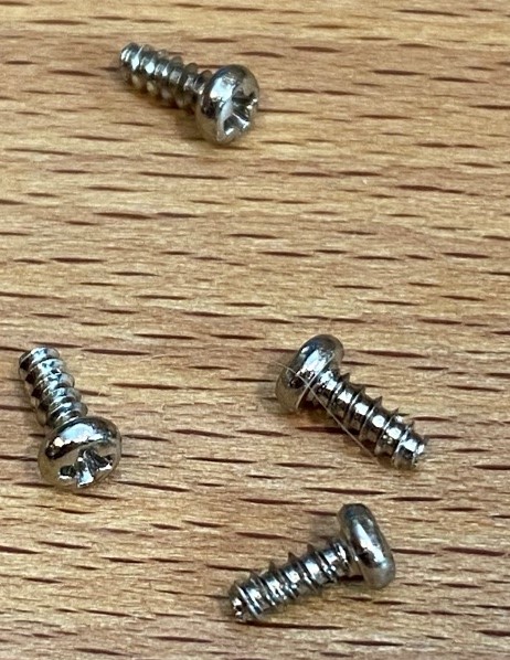
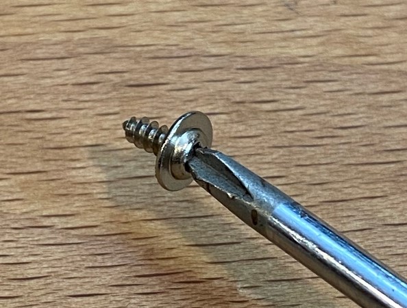
The screws are Phillips drive. These coarse-pitch little fasteners are ubiquitous in plastics products, the threads are sharp enough to dig into plastic and provide a positive hold without tapping holes. They’re made from a low carbon steel with a bright zinc galvanizing to delay corrosion.
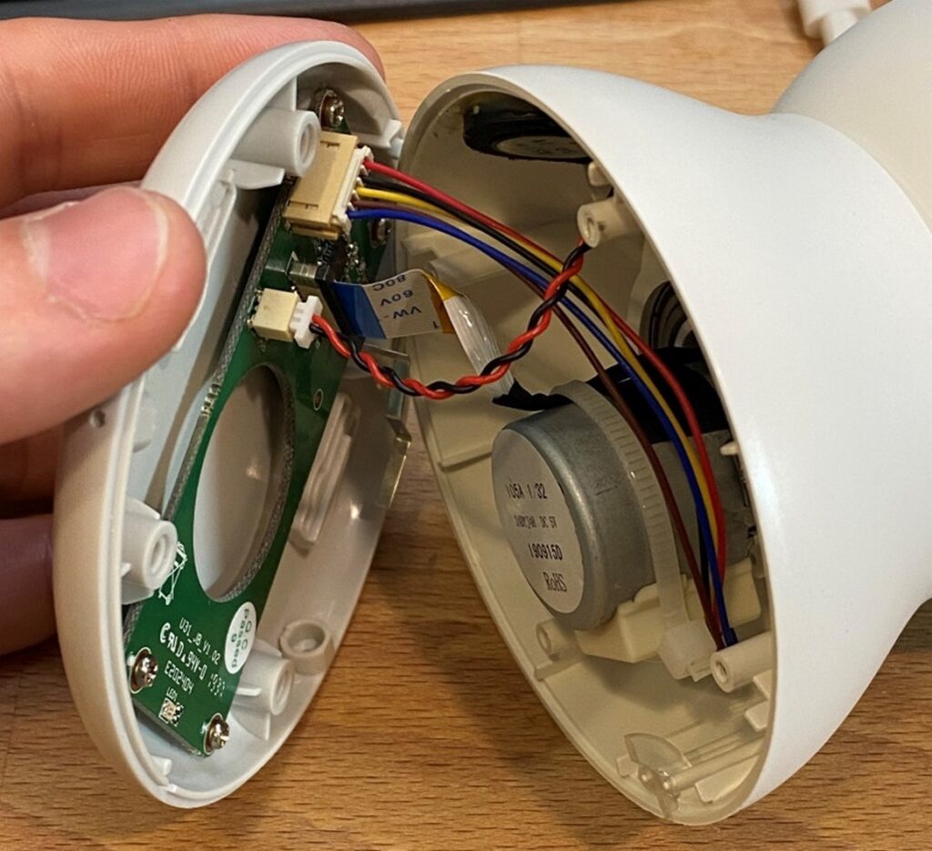
With the bottom plate removed we’re already finding interesting assemblies! I had to un-plug 3 cable assemblies to get the base plate off. Attached to it is a relatively simple circuit board.
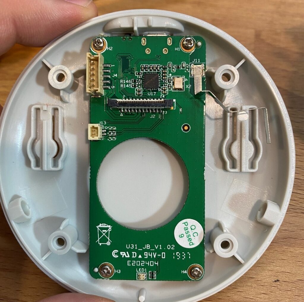
Even though it’s simple, there’s plenty to see on this base board. At the top of the picture, you can see the micro-USB connector and a momentary contact switch, both tucked under the board. The board is reasonably well mounted, using two reference pins and four screws. The reference pins poke through the board beside the top right and bottom left screws. The one in the top right pokes through an oval slot in the board. It prevents rotation around the other pin. My only complaint about the mounting is that the board can be installed backwards by an inattentive operator. Moving say the lower right screw a noticeable bit to the left would solve this issue.
An interesting feature is the folded bit of metal soldered to J11 at the top right. I believe this is a programming pin with hidden access from the exterior of the product. If I’m correct, when the device is assembled prior to packaging, a test fixture slips a probe of some kind in through the keyhole and connects electrically to this bent metal strip. Doing so allows for programming, a factory test, or to put the device in ship mode, likely while communicating through the micro-USB. By hiding this tab and requiring a special tool to ground it, the designers have prevented accidental programming of the device. Cursory tests of this feature, grounding the flag, didn’t reveal its function.
Check out the LED at the bottom center of the board labeled LED1. It’s an “upward firing” LED. Later we’ll see the light pipe which moves light to the surface of the product where it’s required.
I find the large round hole in the middle of this board amusing. Often design engineers need just a little more space for something, and they end up cramming things together. This hole is evidence of cramming. It just provides a little extra space for the motor to fit. The board designer may have missed an opportunity to utilize this space and nest the boards in the panel during fabrication. That would increase the number of boards in a panel and decrease the cost of the boards.
Finally, I want to point out the icon of a garbage can with an X through it on the board. Electronic assemblies like this contain a wide variety of uncommon materials and rare elements. At the end of product life, electronics do not go in the trash. Please take your unwanted electronics to an electronics recycling facility for safe disposal.
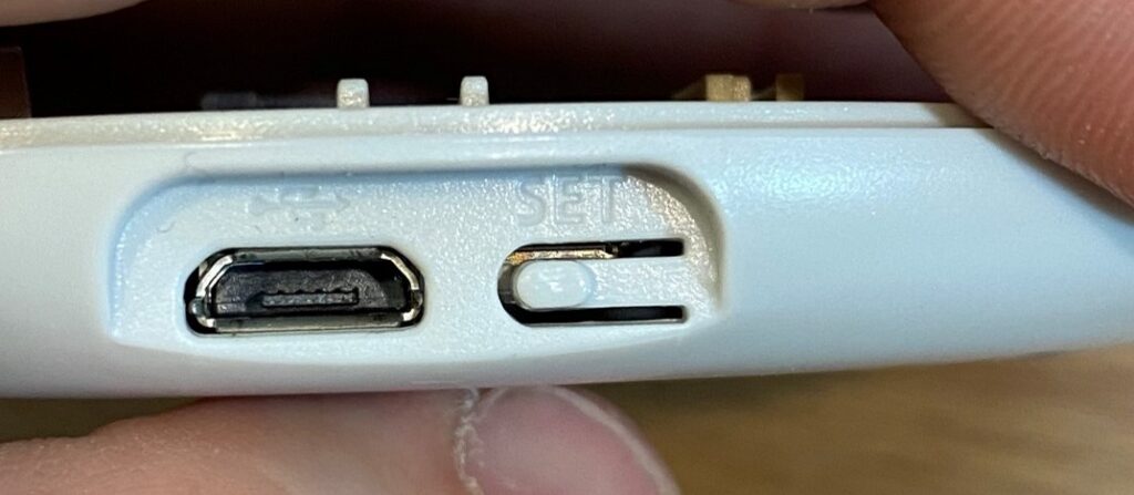
This picture shows more detail on the USB connector and button. This is a low-use button and not an especially robust design. The flexible part of the case acts directly on the circuit-board mounted switch, and force on this button goes through a soldered connection and into the board. Solder connections and circuit boards can handle some loads, but their purpose is more electrical than mechanical. As a result, this switch will not withstand frequent use. High use switches usually will have a mechanical stop to react large forces protecting the circuit board from damage.
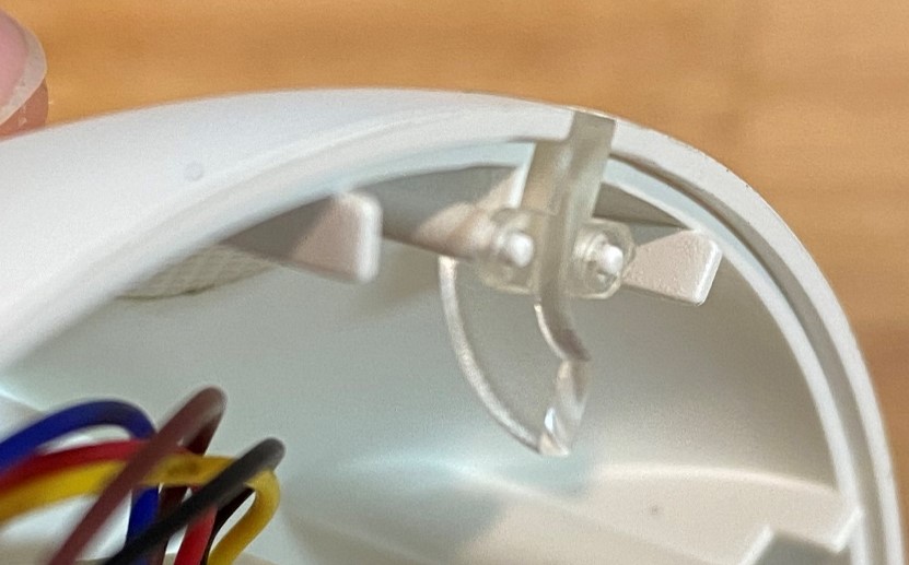
Remember the upward firing LED? It shines into this light-pipe. A light-pipe relies on the tendency of light to stay inside a clear material because of total internal reflection. Internal reflections occur when light rays inside a clear material intersect the surface at a shallow angle. Eventually each ray of light will intersect the surface at a steep angle to exit the clear part. Efficient light pipes have a rough surface finish where light is intended to enter or exit the pipe and polished surfaces where it is intended to reflect. This part sacrifices some optical efficiency for cost by not polishing the reflection surfaces.
Next, I removed the 4 screws holding down the base board to examine the plastic part better.
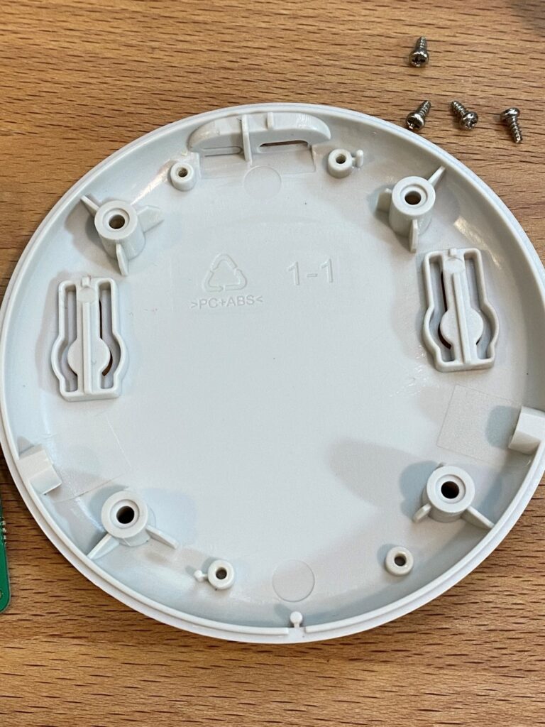
I always find molded parts fun to discuss, and I could write about lifter locations, wall thicknesses and shutoffs for pages. For now, let’s stick to the markings. This base plate is marked as being made from “PC+ABS” a mixture of Polycarbonate and ABS plastics. This engineering plastic alloy is very popular for case parts and enclosures. It offers good strength, good impact resistance, and it hides molding artifacts well. The recycling symbol indicates that this part can be recycled, however it must be recycled with other PC-ABS parts. PC-ABS is a lot less common than LDPE, HDPE, PP and PET used in packaging, which are more commonly recycled.
The “1-1” marked on the part likely indicates that this part came out of mold 1 cavity 1. At high production volumes the manufacturer would likely need more molds and more cavities in those molds. High volume products often use 2-, 4- or even 8-cavity molds. A 4-cavity mold is like having 4 molds in one, with 4 parts falling out of the mold every cycle. It’s important to mark parts with the cavity and mold they came from for troubleshooting molding issues.
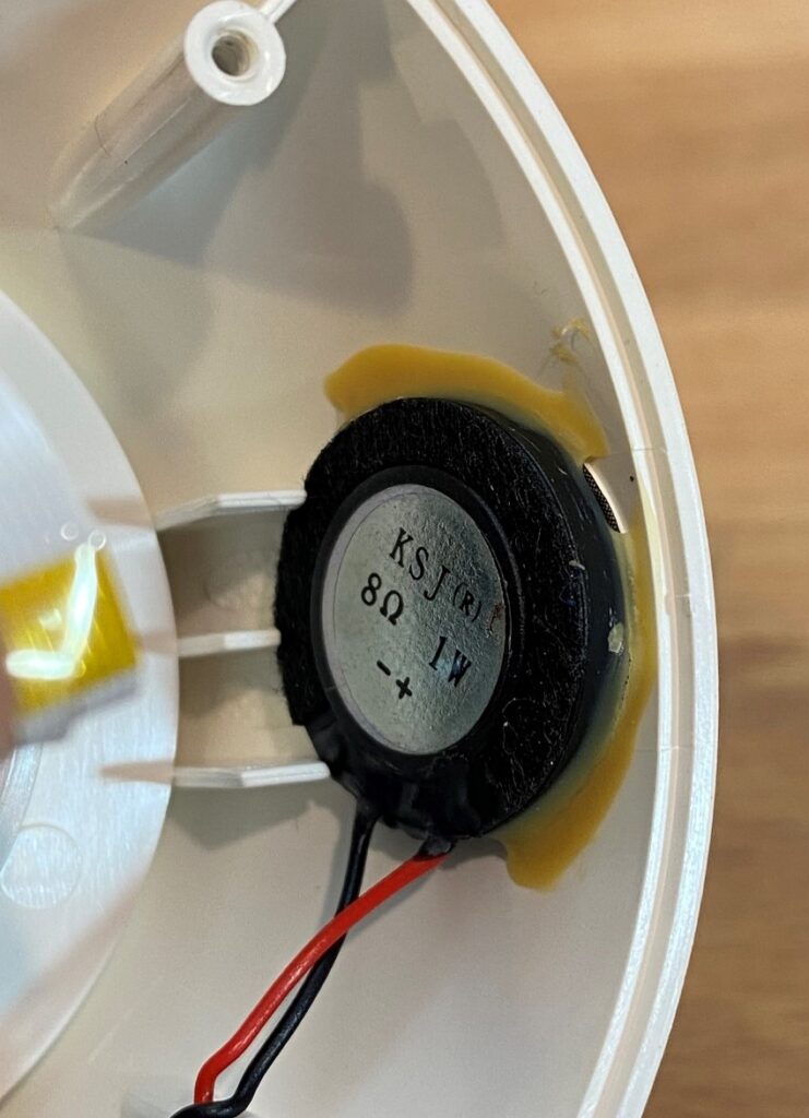
This is the piezo speaker, glued to the inside of the case. To be effective, especially at lower frequencies, speakers need to be installed in a “cabinet.” A speaker moves a “cone” or sheet of material back and forth through the air. While they create the desired sound on one side of the sheet, they also create the exact opposite, noise canceling, pressure wave on the other side. By sealing the speaker on the surface of a sealed box, the negative wave is blocked, allowing the device to produce good sound. There’s a science to how large of a volume behind the speaker cone is ideal, however generally bigger is better, especially at low frequencies.
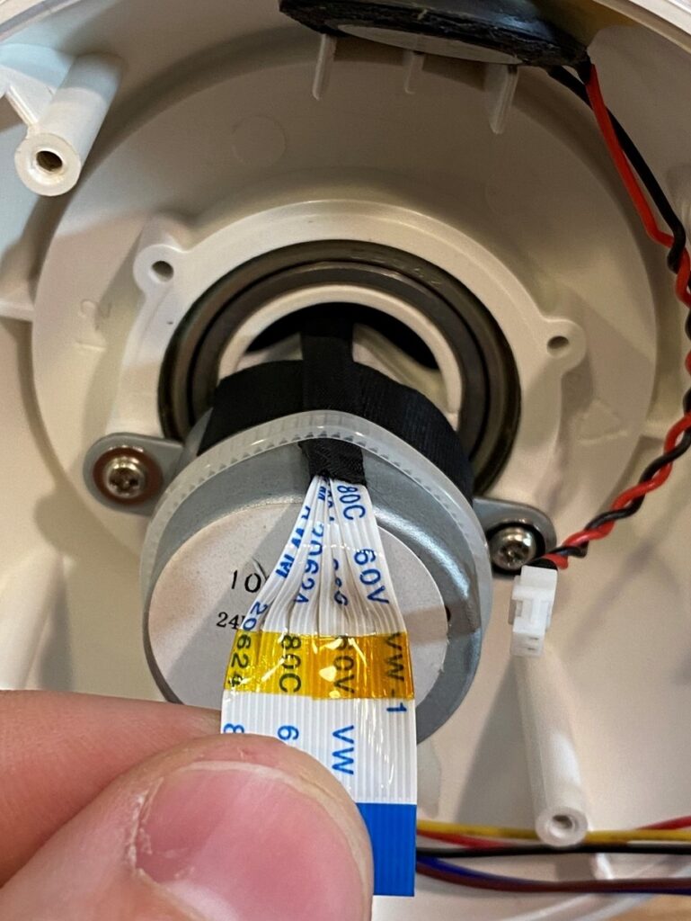
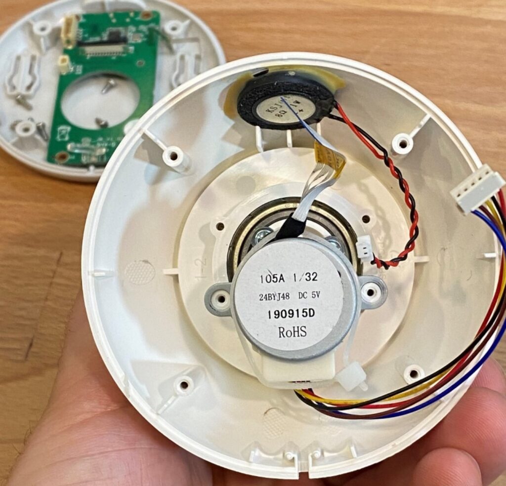
Here we can see the first motor, bearing, wiring, and cable connecting the lower board up to the main board in the gimbal.
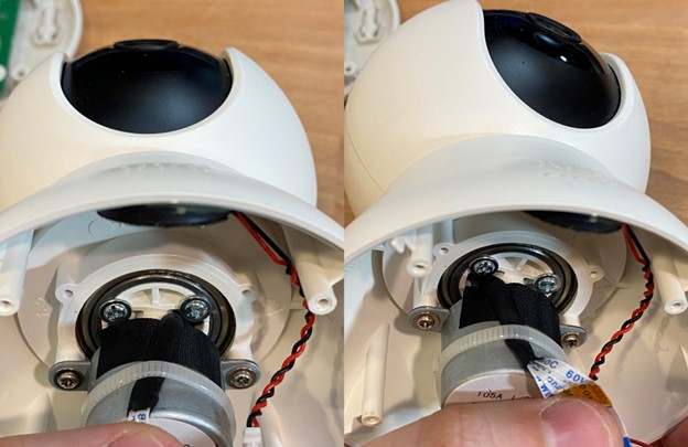
There are some interesting details in the flat flex cable. The flat flex cable allows for the full 360° pan rotation and the tilt motion. Generally flat flex cables only allow articulation in one direction. To allow this this cable to flex both ways, it is split into 6 sections and bundled together. A soft and slippery fabric wrap covers the cable to prevent abrasion. A small strip of Kapton tape prevents the splits from running up the cable into the connector, and a zip-tie to the motor takes the strain off the connector. The ball head of this gimbal can swivel almost 360°, and this cable must flex to allow that much motion. About half of that ball-head rotation requires no movement of the cable, instead the slotted hole in the neck of the device simply moves around the cable. The two pictures above show the head rotated all the way around in opposite directions, showing how the cable flexes.
Two screws retain the motor. These screws have large diameter “washer heads.” Washer-headed screws eliminate the washer from the BOM, some steps in assembly, and possible assembly errors.
The motor has two ears with holes which serve double function: they both locate the motor and serve as screw holes for the fasteners. This system provides more consistent alignment than locating on the screw diameters themselves, eliminating the screws from alignment altogether. However, screw bosses can distort as the fastener is driven, so more accurate location is achieved with separate fasteners and locating features.
Note the elliptically shaped marking on the left side of the plastic. Those marks come from the highly angled ejector pins. See the grid pattern cut into it? That grid pattern helps the ejector to not slide on the plastic as it ejects the part from the mold.
The motor is a five-wire stepper motor. Steppers are common choices for motion control because they can operate without feedback. This device doesn’t have any feedback for the motor, saving the cost of an encoder. Higher precision devices with better motion reliability and efficiency require feedback.
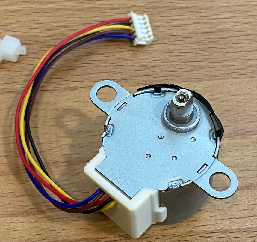
This motor has an output offset from the center indicating it is a “gearmotor”, which is simply an electric motor and a gearbox combined. In most applications, electric motors with the required power output spin too fast with not enough torque. As a result, it’s very common to use gears to reduce the speed and increase the torque of an electric motor. It’s so common in fact, that “gearmotors” are a commodity product.
Looking up the part number for this motor, we find that it is indeed an inexpensive, readily available stepper motor, with a 32:1 reduction gearbox attached. The motor offers 64 steps per revolution, or a step every 5.625 degrees of the motor. Several sources indicate that this particular motor is commonly used in air conditioner louver actuation. It’s available with several different gearboxes. Interestingly, it has an advertised noise level. This gearmotor (5 volt, 32:1 gearbox) is advertised as producing 30 dB of noise. Motor noise is highly dependent on speed and load conditions, and for steppers it’s also dependent on the driver. That said 30dB is whisper quiet, contributing to the quiet operation of this camera motion.
In the camera, the motor output is positioned concentric with the pan axis of the gimbal, which offsets the motor in the case. Torque is driven into the gimbal with a double-D profile, i.e. two flats. This is a common, if weak-for-size, means of driving torque. Double flats are weak for their size because they concentrate the driving load into just two lines on the plastic bore. Further, because the faces are tilted relative to the radius, they also exert an unhelpful outward pressure. As a result, double-D shafts produce high stresses at moderate torques. That said, two flat geometry is easy to manufacture, which is why it gets used often.
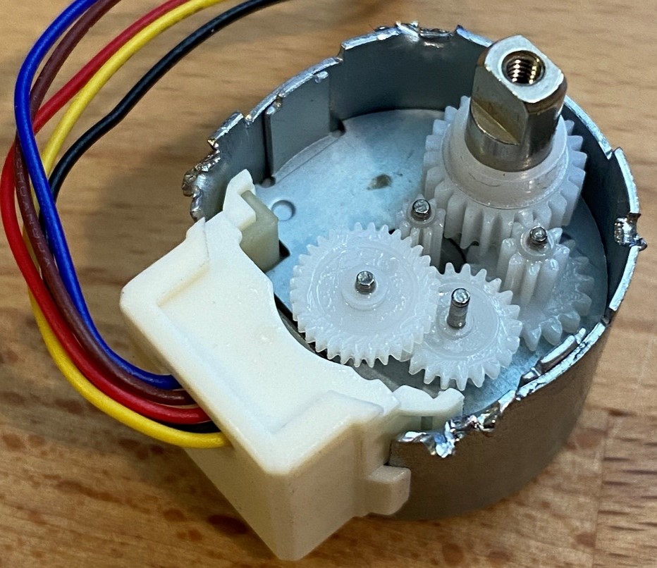
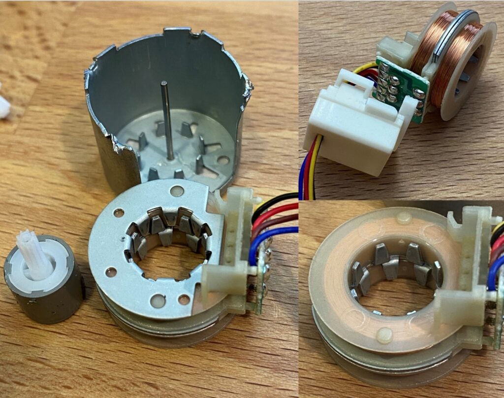
The motor is a “permanent” assembly using little metal folds and crimps to fasten everything together. For my skillset the motors cannot be put back together if disassembled, and you can see the mangle job my needle-nosed pliers did to the motor can. Here we see the gear reduction for this gearmotor. It’s a 4-stage gearbox with spur gears allowing for efficient and deep reduction. Plastic gears are very common in low-cost designs. While they’re tricky to mold they’re far cheaper than high quality hobbed metal gears. Also, plastics are inherently slippery meaning that plastic gears can be more efficient than metal and less reliant on lubrication. That said this gearset is coated in a bit of grease to help with longevity, efficiency, and heat buildup. Note how the gear teeth get larger with each successive stage. Each successive stage away from the motor sees additional torque loads from the previous stage. Also notice how the gears with few teeth are much wider than the gears with many teeth. This is for two reasons. First, it’s beneficial to have one gear wider to maintain good engagement regardless of axial misalignment. Second, the gears with fewer teeth are weaker, and the additional tooth width helps compensate for the weakness. As tooth count goes down, gear teeth get thinner at the root to achieve tip clearance for the mating gear. A wider gear helps strengthen those teeth.
This motor is a 5-wire stepper motor, but interestingly it doesn’t have the radially set of electromagnets normally seen in steppers. This design saves winding cost by wrapping just two large axial coils and then uses sheet metal features in the steel motor casing to guide magnetic flux, putting magnetic poles where they’re required.
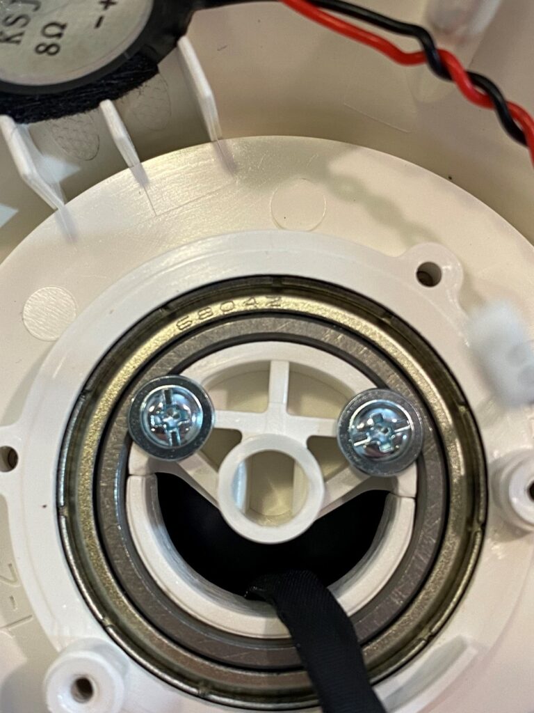
With the motor removed, it’s smiling at us! Faces turn up in product design now and again. On the nose, you can see the double-flat bore which the motor engages. Two more washer-headed screws retain the head of the gimbal to the large ball bearing. It is surprising to see this large ball-bearing here. This 6804Z bearing is an expensive part for this consumer-grade device. The bearing is shielded, metal plates help protect against dust. Important for this application, the shields also help retain lubricants in the bearing. With hundreds of pounds of load capacity, the bearing is overkill. However, it does provide a way of achieving smooth, silent motion with no slop. Furthermore, this joint connects the ball head to the base plate and is an area where a customer would notice slop handling the device.
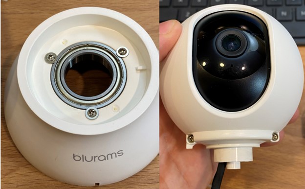
Removing the two washer headed screws “eyes” from the bottom of the ball allows the ball head to pop off the base. Just two screws fasten the two hemispheres of the ball head together. In this view the hard stop for the panning feature is visible. There is a small tab adjacent to the left screw on the ball head which interacts with the rib on the right side of the base. We can see how this will allow nearly 360° of motion for the head. Both ribs are about 1.5mm thick and the radius is about 24mm, meaning only about 7° of unavailable travel. The designers of this device have cleverly placed this dead zone where the camera can’t pan at the “back” of the base so if the camera is installed in the intended orientation, it can pan all the way to the back either direction.
This concludes the first part of disassembly. We learned about the pan axis, button protection, light pipes, and the motor used. We also got to see how a ball bearing might be used to add a feeling of quality to a low-cost device, saw how the speakers worked, and indulged me in a discussion of fasteners.
Next time we’ll open that ball head, and have a look at the elevation axis, the camera features, some challenging plastic molding and discuss why the black plastic part is a different material than any of the white plastic parts.
See you in the second part of this Pan-Tilt Security Camera Teardown blog!

