When developing software for use in the medical device industry, best practices must be followed to ensure regulatory requirements are being consistently met. As we dive into software development in the medical device industry, let’s take a look at the product development process and how it relates to the regulatory requirements of IEC 62304.
Specific development standards and regulatory requirements exist for different industries. In the medical device industry, for instance, ISO 13485 defines requirements for a quality management system that demonstrates the ability to create medical devices that meet customer and regulatory requirements.
Because of the inherent complexity of software systems, software development has become more tightly controlled than hardware in regulatory environments. Thus, standards have emerged to guide this process specifically for software. For medical devices containing software, the software must be developed according to IEC 62304.
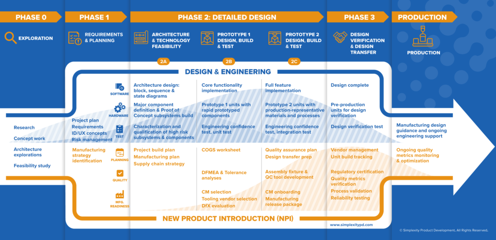
The processes put forth by IEC 62304 are really established best practices in the software industry, most of which can be followed for both medical and non-medical projects. The standard does not prescribe a particular life cycle model or documentation structure, only that the activities and tasks be completed. The activities described in 62304 fit neatly into many phase-based product development approaches. In this instance, we will reference the phase-based product development approach summarized in the graphic below.
Phase 1: Requirements and Planning
The software development plan is a living document that guides the development process for the project. It outlines the software tasks to be done and what roles are responsible for those tasks. In consulting, where the responsibilities could fall to the client or to the client’s engineering design partner, it is especially important to clarify ownership of tasks. The software life cycle model must be decided at this point. Will the project follow Agile? Waterfall? Or a middle ground, an incremental approach? Some engineering design firms offer processes that are more flexible than others so establishing this early is key to ensure the design partner’s processes are flexible enough to respond to client needs.
The plan identifies software milestones and outlines which features belong at which milestone. One common milestone is to ensure there is enough software available to test the hardware from the first prototype build. This document will be updated in every phase of development, and by the end of the project it must match the reality of what was actually done.
The software requirements specification is derived from the product requirements, which are also developed during Phase 1. The software requirements include the functional and capability requirements, software system inputs and outputs, interfaces, security, and usability requirements. In addition, any risk control measures determined from the risk analysis must be added as requirements.
Phase 2A: Architecture and Feasibility
The architecture activity is where the software requirements are mapped into an architectural explanation of the software’s structure. Typically, this includes a high-level block diagram showing how the software interacts with the hardware as well as system-level state and sequence diagrams to describe the behavior of the software system.
Relating back to the medical device standard, in the language of IEC 62304, software is described with three terms:
- Software system – the top level, composed of one or more software items
- Software item – any identifiable part of a computer program. It is composed of one or more software units
- Software unit – the lowest level that is not further decomposed (The level of decomposition is determined by the project team. It is NOT required to have each class be a unit.)
It is important for the architecture to identify software items, as they will be analyzed during the risk management process.
The architecture must also describe interfaces between the software and internal or external components such as the interface between two software items, two processors, or the processor and a mobile application.
During this phase, an initial software risk analysis would be run, and a preliminary software safety classification determined.
Phase 2B/2C: Detailed design
Detailed design typically has multiple iterative sub-phases (2B, 2C, etc) in which three software activities must be completed:
- Detailed design fleshes out the details outlined in the architecture. Each of the items identified in the architecture is divided into software units and described in enough detail to allow implementation to proceed.
- Unit implementation and unit testing is the part that software engineers love – the actual coding! The implementation of a unit is not complete until it has been unit tested and the code has been reviewed by the team.
- Software integration and integration testing
During detailed design phases it is more difficult to align software and hardware development. Hardware typically follows a design-build-test strategy, with project phases aligning with the hardware builds. Software development, however, has no need for an artificial boundary between the hardware builds. Yet at the same time, the hardware must be tested using functional software or firmware. One effective strategy is to determine what software features are necessary to verify the hardware. Completion of those features can serve as milestones (outlined in the Software Development Plan) for early design phases. By the end of the final design-build-test phase the software should be feature complete.
In addition, it is not necessary to complete detailed design of the entire system before implementing particular modules, so an incremental model is an acceptable approach. Design reviews, another best practice required under ISO 13485 and IEC 62304, would be completed at appropriate increments or milestones as portions of the design are completed.
As much as possible, it is best to automate unit testing for projects. This facilitates a streamlined weekly release process that runs static analysis, creation of the output binaries, and executes unit tests.
Phase 3: Design Verification and Transfer
In Phase 3, the team’s focus turns away from development and towards verification. The software system verification test protocols were released in Phase 2, typically written by the quality engineer with input from the software engineers, and the team executes dry runs and fixes final issues with the software or the protocols themselves.
Before formal verification, the software team prepares a candidate release build, including release notes which contain lists of known issues, added features, and fixed bugs in this version. This software build is the version that will be used during formal software verification testing (SVT). Though this version is often casually referred to as “released software”, it is not officially released until it has passed SVT.
During formal verification, it is important that the tester NOT be any of the engineers involved in writing the software. Any issues or anomalies found during testing during this phase will be documented in the issue tracking system to be evaluated by the project team.
Formal verification of the software happens along with the overall design verification testing for the product as a whole.
Conclusion
The formality of documentation may differ, but the best practices of planning, writing down requirements, performing code reviews and different levels of testing are best practices that should apply to all projects.
If you need help designing a new product to medical device standards, please contact us so we can discuss your options.


