
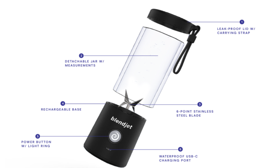
The BlendJet 2 may appear to be a simple, portable single-serve blender, but beneath its sleek exterior lies a carefully engineered combination of mechanical and electrical components. From its compact form factor and rechargeable battery to its waterproofing and motor assembly, every aspect of the design is optimized for durability, portability, and performance. The device is small, rechargeable through a USB-C connector, and can seal liquid contents. In this teardown, we’ll take a closer look at the BlendJet 2’s internal structure, explore key design decisions, and analyze how its components come together.

Photo: BlendJet
Although the device may look simple on the outside, we will take a deeper look inside to see the mechanical and electrical components and to point out some of the notable design choices.
Mechanical Design Teardown
The BlendJet 2 consists of three major assemblies: a lid to seal blended contents inside, a jar which is essentially a threaded hollow cylinder to store and view the blender contents, and a base which houses all of the electronics.
High-level Assembly Components

Jar
Notice the grey permanent magnet on the bottom rim.
This informs the MCU that it is safe to operate the blade!
 Blender Base
Bottom Case Part
We will focus this on the blender’s base, and start disassembly from the bottom. To hide the screws, there are three rubber feet “plugs” that may be removed with a flat head screwdriver to reveal the screws. These rubber feet are pressed into the bottom case part. You may have seen adhesive rubber feet on other products that are more likely to fall off after vigorous use. Considering that the blender is designed to be portable, it is no surprise that the rubber feet are pressed into the bottom case part for added longevity. The rubber feet are easy to insert and remove, but they still have strong enough press fit to be very secure in normal use.
Also note the use of thread-forming screws: these screws are commonly used in low-load consumer devices, and they carve threads in plastic holes to keep parts together. The alternative would be to use nuts, which can add unnecessary cost and assembly time.
Bottom case part with one rubber foot removed
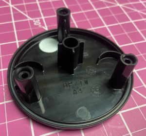
Bottom case part internal features
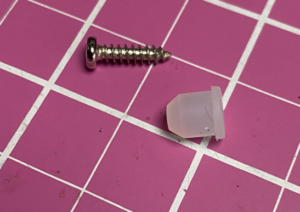
Detail of thread-forming screw and rubber foot
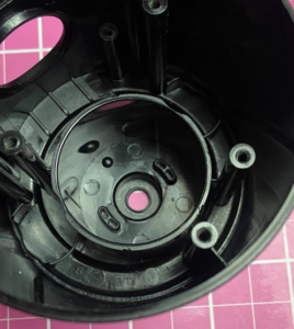
Removing the bottom case part shows a white disk still mounted on the case. That disc creates a waterproof seal on the base’s exterior while allowing the enclosed volume to equalize with external pressure.
Base Electromechanical Components
Looking into the main open body of the base, we can see some tightly packed electromechanical hardware! Removing the black retaining bar above the motor using the two visible screws allows us to see the main electronics: a motor, 2 batteries, and a control Printed Circuit Board Assembly (PCBA).
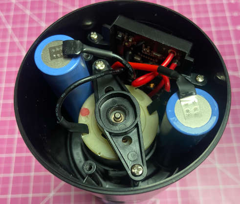
View inside base once bottom case part removed
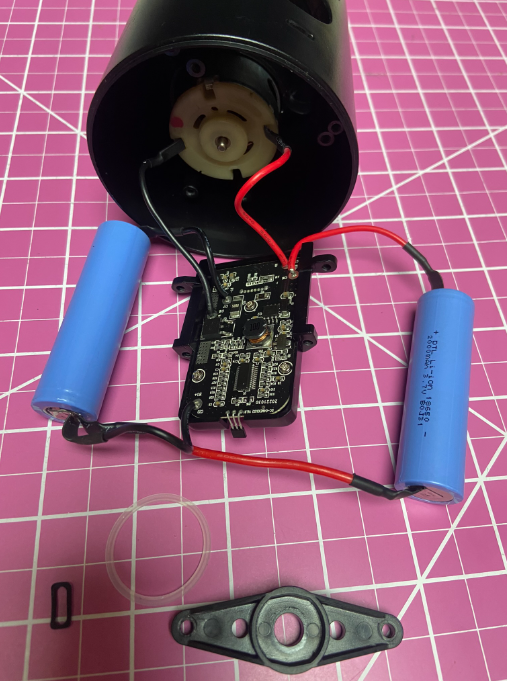
Main electromechanical components and gaskets
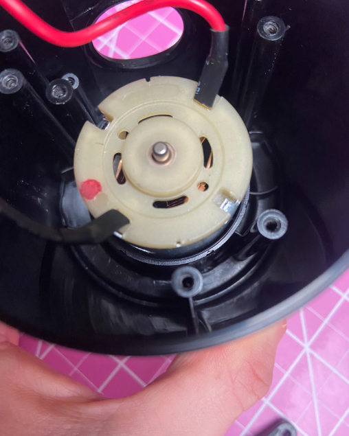
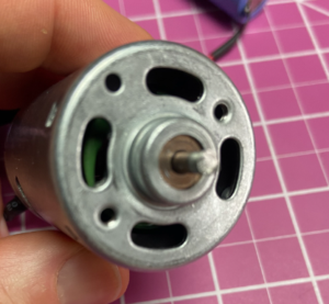
Motor installed in base
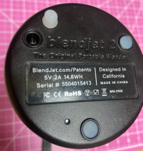
From reading the marking on the batteries, we can see that they are both 18650 size, 2000mAh 3.7V Li-ion cells. Although the batteries appear to be wired in series, you may notice a black wire attached at the node between the two batteries and the board. This third wire is likely used for cell balancing, a method to maximize the state of charge of each battery as one cell will often charge or discharge faster than the other.
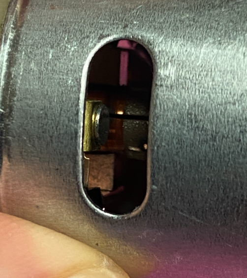
The motor is a brushed DC motor because you can see leaf-spring brushes through the plastic motor end cap and because there are only two wires leading out of the motor. Although brushed motors generally have a lower service life, they are generally cheaper than other brushless designs, and the motor duty cycle is relatively low (we would expect only a few 10-second blends per day).
Disassembling the base further, we also removed the rubber gaskets that seal the on/off button and USB-C port against the housing.
Blades and Motor Removal
The blender blade appears to have been permanently pressed or crimped onto the motor’s 1/8” steel shaft after the motor was assembled in the base. The blades prevented further disassembly of the motor, and they could not be easily removed, so we used a hacksaw to cut through the motor shaft and remove the motor from the housing.
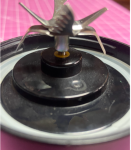
Multiple Blades Installed on Shaft
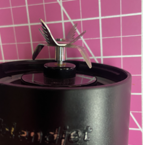
Blades are pressed/clamped very firmly. Upwards facing blades alternate smooth to serrated.
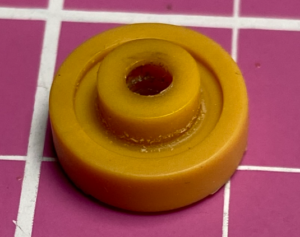
Motor seal, top side
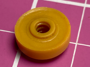
Motor seal, bottom side
After removing the motor, we found a yellow seal to keep the liquid blended contents out of the base enclosure. Looking closely at the inner diameter of this seal, you can see four ribs to stop liquid and debris from passing between the seal and the motor shaft while it is turning. The outer annulus on the top of the seal would not be rotating, so the seal is achieved purely by the compression force of the motor installation.
On the blade side of the motor, there are some oblong arc cutouts in the motor housing. To keep the motor in place while rotating, there are boss features in the housing that fit into these cutouts.
Oblong arc cutouts in motor housing
Matching rotation constraint features in base housing
The Button Carrier
The control PCBA is attached to a carrier assembly that was injection molded using several molding cycles (overmolding). The button is quite thin, has a screen-printed logo on it, and the concave features align to a momentary switch on the control PCB. A flexible rubber that suspends the button in the black plastic carrier was likely the last step in the overmolding process, and the rubber has recessed features to serve as a light pipe for LEDs on the control PCBA.
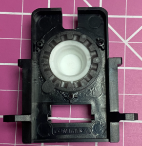
Carrier, PCBA side
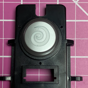
Carrier, user side
Control PCBA and Electronics
Looking at the user side of the control PCA, there are 12 red/blue LEDs in a roughly 1.5 inch diameter circle and four white LEDs that encircle the central momentary button at about 0.5 inches in diameter. There is a hall sensor at the top overhanging the board, and a USB-C connector that is normal to the board. The hall sensor detects whether or not the jar is installed so that the blade will not rotate if the GPIO line from this binary hall effect sensor is tripped. The device will happily charge without the jar, but it will not spin the blades. Safety first!
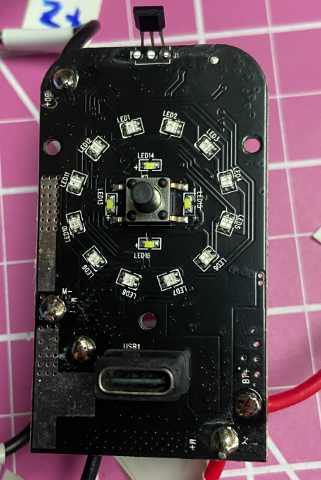
In general, PCBA soldering and assembly processes are cheaper if all components are on one side, and you will notice the rear of the Control PCBA has most of the components.
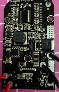
From looking at the chip marking and package, probing the PCB, and comparing the components to available datasheets, some educated guesses may be made about the key components on the board. Some of those components are listed below.
-
Unmarked 24-pin microcontroller: The microcontroller unit, or MCU, is often the largest component on the PCB, and this one is labeled U1 at the top.
-
CC6201 Omnipolar Hall effect switch: This sensor has a digital (on/off) output to tell the microcontroller that the jar is installed so that it is safe to run the blade.
-
FDS6630A N-Channel MOSFET: Charges the battery with a protection diode and a power inductor.
-
7550 5V voltage regulator: Maintains the 5V rail for the MCU and hall effect sensor.
-
SM3113 Mosfet: Low-side driver for the motor. From probing, it was found that the high side of the motor is connected to the battery at 8.4V.
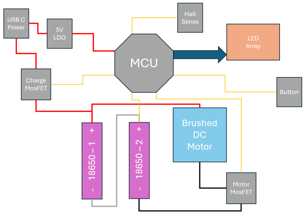
We generated a high-level system diagram showing how these components interact with one another, shown below.
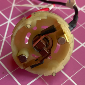
DC Motor Exploration
Returning focus to the 35.5 mm diameter motor, two access windows on either side of the motor near the commutator and brushes are visible.
Let’s pry it apart to get a closer look! The two large magnets in the motor case (stator) need to be kept separate. To achieve this, the sheet metal motor case has some lance features on one side of the magnets and a leaf spring inserted between the two on the other side. At the bottom of the motor case is a bronze bushing to guide the motor shaft.
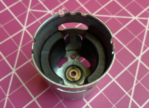
Inside motor case, lances separate magnets
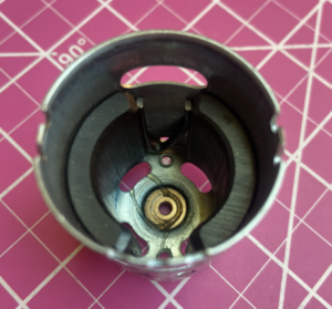
Inside motor case, leaf spring separates magnets
The other half of the motor holds the rotor assembly with the shaft, coils, and brushes. There is another bronze bushing in the plastic stator end cap to guide the opposite end of the shaft, but this one is captured in a spherical joint. The joint is used to avoid over-constraining the design and ensure there is some “wiggle room” for the bushings to align to each other during assembly.
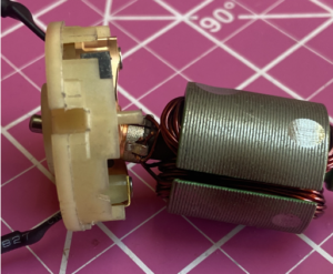
Spherical joint and bushing
You may also note the mark on one side of the rotor; this is likely material removed before assembly to balance the rotor and remove eccentricities.
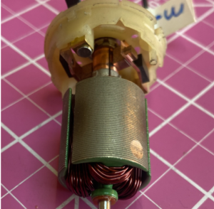
The isolated rotor also shows red composite washers on the shaft that react against axial loads with minimal friction.
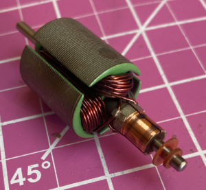
Rotor detail
Stator cap with brushes
Conclusion: BlendJet 2 Portable Blender Teardown
After taking apart the BlendJet 2, there are some clear signs that the design has been intended for medium-to-high volume production where simplifying the design, reducing material costs, and reducing assembly time all have significant impacts on the overall profitability of the device. The injection molded case, the brush motor, thread-forming screws, a single motor seal, and the overall limited part count are tell-tale signs of a design that has effectively taken cost into account.
The press-fit rubber feet and white membrane on the bottom of the base also show some amount of design maturity. These features are not necessarily the cheapest and easiest design choice, so these additions were likely some of several optimizations made from earlier versions of the product meant to enhance the product’s reliability.
On the other hand, if the designers are targeting even higher production volumes with reduced per-part costs, some additional design updates could be considered. There is a black plastic motor retainer part that could conceivably be eliminated by adding features to the lower case part or adding customizations to the motor housing. Wiring and soldering can also be a relatively expensive assembly process. The wiring to the motor could be eliminated by mounting and soldering the motor to a reoriented version of the control PCBA. Similarly, the wires between the batteries and the control PCBA could be eliminated using battery packs where the welded battery contacts have features to interface directly with the PCBA. However, these updates are likely not cost-effective for the intended volumes.
We hope you have learned a bit about the BlendJet 2 and enjoyed the disassembly process. We’ve been able to uncover some interesting features of the design and expand our understanding of some of the design decisions. For input on how your designs could benefit from Simplexity’s product development expertise, feel free to contact us!
YOU MAY ALSO LIKE:
- WATERPIK AQUARIUS WATER FLOSSER ENGINEERING TEARDOWN
- TOP 10 ADVANCED TIPS FOR DESIGNING PLASTIC INJECTION MOLDING PARTS
- SHARK AI ULTRA ROBOT 2-IN-1 VACUUM AND MOP TEARDOWN
This is an independent teardown of the BlendJet 2 Portable Blender. If you have any questions or service requests, please contact BlendJet directly. Simplexity is not affiliated with or able to assist with the product featured in the teardown.