There is a lot of hype about 3D printing. 3D printing technologies have been transformative in many industries, including product development. With 3D printing we can get complex geometry in small and medium parts quickly and inexpensively which makes it extremely valuable in prototyping. In product development, 3D printing is often a steppingstone to high-volume manufacturing methods. We use 3D prints to quickly and inexpensively create parts for prototypes. Prints ease and speed the prototyping process, allowing faster iteration of designs. The short lead times and low costs associated with 3D printing technologies shorten early prototype design cycles. However, 3D printed parts for protos aren’t without limitations.
Because prototypes are about learning, and 3D prints are different than production parts, it’s important to learn only the right things from 3D prints. Some problems with prototypes will be caused by the 3D printing itself, whereas some are caused by the design. Here I want to discuss 3 areas where 3D prints are different than production plastics, primarily injection molded parts. The differences are in their surface properties, their tolerances, and their strength properties. Then I want to look at how a design engineer can work around these limitations in their prototypes.
1. Surface Finish & Tribology Differences Between 3D Prints and Injection Molded Components
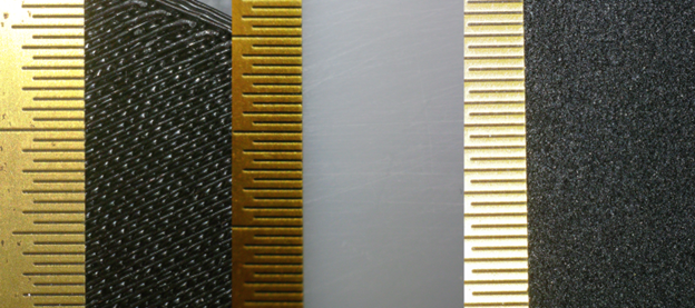
The first key difference between 3D prints and molded components is in their surface properties. Most 3D prints have pretty poor surface finish. Fused Deposition Modeling or FDM 3D printing provides a very layered surface finish, where you can clearly see the printed layers stacking on top of another and, at the surface, each layer bulges and dips. Selective Laser Sintering, PolyJet, and Multijet Fusion all provide a sandy surface finish. This surface is less directional than FDM, but it’s rough.
Stereolithography or SLA 3D printing provides the smoothest surfaces, but they have high surface energy: they’re grippy. SLA parts are born in a bath of glue. All of these technologies produce parts with surfaces very different than the slick surfaces of injection molded parts. Sometimes that doesn’t matter, but sometimes it makes all the difference. Surface properties are particularly important when it comes to tribology.
3 different 3D printing technologies’ surface finish. Each is photographed with the same gold-colored steel ruler showing a line every 0.5mm. Left: FDM. Center: SLA. Right MJF.
The tribology, i.e. the friction and wear characteristics, of 3D printed parts will be different than molded parts. Both the friction and the wear tend to be higher with printed than with molded parts. There are a few reasons for this, depending on the 3D printing technology and material. Rough surfaces from many 3D prints add friction and the voids in that roughness increase wear rates. Stereolithography parts have very high friction surfaces which are surprisingly grippy for their smoothness and hardness. The friction itself causes rapid wear of these parts. Friction can be very problematic when designing mechanisms with moving parts, like sliders, doors, gears, and bushings. The surface properties don’t only affect tribology, but also affect cosmetics, adhesion and appearance of coatings and paints, as well as how the parts interact with adhesives, all of which can be important for prototypes. Not only can the surfaces of 3D printed parts be rough, they might also not be where you expect them to be, because 3D printing can have loose tolerances.
2. The Fallacy of Testing Tolerances Using 3D Printed Prototypes
In the mindset of prototyping, there is a strong drive to “test” tolerances along with everything else in a prototype build. To test some tolerances, you might check that a stack-up of parts fits together, or measure the actual clearances between parts. If the stack fits, or if the or the clearance is correct, then it may be taken as evidence that the tolerances are correct. This is a great type of testing to perform on pre-production parts using production intent tools. However, with 3D printed prototypes this test would provide bad data because of two big limitations with the approach. First, the test is a test of 3D printed parts’ tolerances not production tolerances. Second, usually 3D printed prototypes are very limited in number of samples, giving poor statistical power.
Testing tolerances with 3D printing when molding is the intended manufacturing process is testing the wrong thing. The 3D prints will have different tolerances than production parts. When compared with injection molding, 3D printed parts tend to have substantially looser tolerances. There are many more possible causes of variation in parts 3D printing than injection molding.
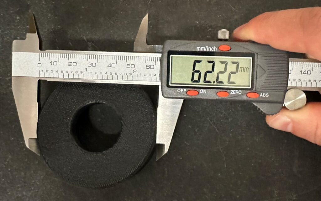
This part is nominal 62.00mm in diameter. With FDM’s limited tolerances, it measures 62.22 at the largest rotation. Tolerances in 3D printed parts are generally a lot looser than in injection molded parts.
Sample size is usually also a problem for testing tolerances in 3D printed prototypes. To learn about actual variability in an assembly, you will need a statistically representative sample to have confidence in the data. This is often 25, 50 or 100 samples, i.e. prototypes. Prototype builds in this quantity rarely involve 3D printing because, at this quantity, molds tend to become financially viable. Usually, 3D printed prototypes are made in much smaller quantities. With the low sample sizes and the differences in tolerances between 3D prints and molded parts, any test of tolerances is likely to generate uninformative data. It’s usually not possible to generate learnings about tolerances from 3D printed prototypes. The differences are more than just at the surfaces.
3. Mechanical Strength Properties of 3D Printed Parts
Another area where 3D prints are not representative of molded parts is in their mechanical properties. Despite the hype around certain materials, 3D prints are simply not as strong as comparable molded plastics for several reasons. First, the materials and processing of 3D prints tend to be weak, second 3D printed parts tend to have anisotropic strength properties, and third, 3D printed parts tend to have much lower toughness than molded components.
The plastics available in 3D printing combined with the way they’re processed in the 3D printer tends to make them weak. Manufacturers of 3D printers and materials will print test samples and report ultimate strength data on them. Ultimate strength is the pressure within the material that causes it to break. These values are usually lower than similar plastics molded, sometimes a lot lower. Some 3D printing materials will add carbon fiber as reinforcement, though these are rarely worth the effort. Almost always these carbon fibers are very short, limiting their reinforcing capabilities, and they never cross layer lines. Which brings up an interesting factor of 3D prints, their anisotropic strength.
Printed parts are anisotropic: they have different strength in different directions. Usually, 3D prints have the best strength in the plane of the layers. The addition of reinforcing fibers, usually carbon fiber, can only strengthen the material in the plane of the layers. To be able to use the strength of anisotropic material, a designer must orient the loads in the direction of the part’s strength. While on some parts this is easy, in others it takes thorough analysis and even testing. If load analysis isn’t performed, and layer orientation is not controlled, anisotropic materials are almost always weaker than expected. In addition to the ultimate strength, or the load a material can hold without breaking, there are other types of strength which matter.
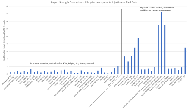
One important type of strength is impact strength or toughness. Impact strength comes from a combination of load supported and the distance distorted. To have high impact strength the part must resist high loads and deform a lot. When tested, not only do 3D printed parts tend to break at lower forces (stress) but also much lower distortions (strain) than molded counterparts. Impact strength is roughly proportional to stress times strain (though it also depends on a material’s notch sensitivity and strain-rates sensitivity), so 3D prints have dramatically lower impact strengths. In the business of consumer product development, impact strength is very important. The carbon-fiber reinforced 3D printed materials suffer particularly here. In carbon-fiber reinforced 3D prints, the carbon adds stiffness without adding much strength at all. This is disastrous for impact strength. Impact strength is the foundation of drop resilience. Achieving good drop resilience is critical for many consumer products. With many 3D prints having 80% less impact strength than their molded counterparts, teams can learn very little by dropping 3D-printed prototypes.
Impact strength comparison. The left is a selection of 3D printed materials. The right is a selection of Injection Molded materials. The chart demonstrates why it’s challenging to pick a material from the right side to represent a material from the left. Especially true when the components where impact strength matters will often be made from Polycarbonate, ABS or a blend of the two.
How To Get the Most Value from 3D Printed Prototypes
With all these differences between 3D printed and molded parts, it’s important for a design team to understand these differences, and sometimes to limit expectations of 3D prints. Most of the time, 3D prints still have value, and I want to spend a little bit of time exploring how to get value out of 3D printed prototypes and how to move through the development process quickly using 3D prints for prototypes.
It’s important to note that there are many, many components in products, especially consumer products, where the performance parameters mentioned above are not critical. With these parts, nothing slides, or wears, they’re plenty strong, and the tolerances aren’t critical. These are the parts where we lean heavily on 3D printing without additional risk or analysis. It’s key for designers to identify these parts and use 3D printing as a quick and inexpensive way to get through prototype builds. But almost every product has parts where this isn’t the case, where tolerances, surfaces, or strength matter. So, what should a design team do to move efficiently and learn effectively from prototype builds?
Almost all of the differences between molded and 3D printed parts make the 3D prints “worse.” That means, that if the design is working with the 3D prints, it will have margin in the product. One option is to release the product with extra margin. For friction, extra margin is designing the machine to function with or overpower the 3D print’s high friction. For margin against wear, a design might include large wear surfaces to extend life. For margin against loose tolerances, parts may fit with extra clearance between them. For strength margin, designs may use overbuilt components, extra ribs and more nominal wall thickness in plastic parts. I’m a big fan of adding margin wherever I can. Adding margin to a design is a great way to reduce risks of problems, fight fewer problems in the development cycle, and often makes designs less dependent on fancy materials or specialized processes.
Additions To Make 3D Printed Prototypes More Production Representative
We can’t always just add margin though, so how can we learn effectively from our prototypes? For wear and friction, inserts can help. These can be simple, like off-the-shelf bushings or small, flat, laser-cut sliding plates made from the production material. For strength, it is often necessary to use other prototyping methods, in particular machining. When impact strength matters, the relevant components should be machined out of a single piece to generate useful learnings. Sometimes using a bridge or soft tool mold is best.
Design teams shouldn’t try to test tolerances in a prototype assembly without production plastics. It’s far better to spend the effort that would be spent testing protos for tolerances and put that effort into a thorough, careful, team-reviewed tolerance analyses.
Conclusion
In the end, prototypes are about learning. You build prototypes to gently and carefully confront the theory of the design with the uncompromising realm of reality. Prototypes present to the design team some of the problems they didn’t anticipate, before taking the plunge of expensive production tooling. With that said, it’s important to learn only the right things from prototypes. Establish learning goals for a prototype build, choose prototyping techniques appropriate for the learning goals, and use 3D printing to its fullest advantage.
If you need help with your prototype development and optimization efforts, contact us to learn more about how we can help you with your project!


