Introduction
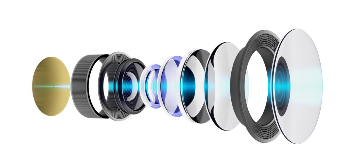
Optical systems have always been important, and today they are more important than ever. Even before engineering, before lenses and curved mirrors, optics were important to animals with eyes. Optics are a very powerful way to understand the world, and they are more important than ever. Today, in the increasingly robotic world of technology, our machines use cameras and optics more and more. From vision systems for automated inspection, to robot guidance, to the optics in your cell phone, to the mirrors and lenses used in lasers, optical systems are more important to machines than ever. Optical technology might be as old as animals with vision, but the mechanical integration of optics is still a fun, interesting, and difficult engineering challenge.
Things to geek-out about!
- W-shaped pupils in cuttlefish. The cephalopod eye is much like the eyes vertebrates have, even though cephalopods are in most other ways completely unlike vertebrate.

- Modern land-based high-power telescopes – The new ones have actuators all over the back of the mirror which distort the mirror to compensate for atmospheric aberrations.
- Metal Cutting Lasers – High powered modern lasers routinely cut steel over an inch thick in manufacturing. This process is now inexpensive and widespread.
- Binocular Vision used to judge distances in machine vision. Subaru active cruise control uses this instead of radar to judge the distance to the car in front.
There are many challenges associated with successfully integrating an optical system into a product. In fact, many engineers find designing products with optics particularly difficult. The challenges are ones which occur in other types of mechanical engineering design problems. They can all be solved with good mechanical engineering. However optical problems tend to highlight certain engineering challenges in ways that other mechanical engineering tasks do not. Because optical systems highlight these challenges, and unify them into one design, optical design can be frustrating. Here is a list of five challenges facing the designers of an optical system and solutions to those challenges.
Optical Systems Challenge #1: Managing Tolerances
When the Hubble Space Telescope was set into orbit, some of its first images were broadcast on TV for the world to see. They were blurry. Hubble’s main mirror had been ground ever so slightly wrong. The error was that the mirror had been ground in earth’s gravity. On earth, the mirror was right. But when placed in orbit, with no apparent gravity, the mirror distorted. In fact, the mirror’s own weight had been holding it in the proper shape. With its weight removed, the mirror distorted. A small corrective lens was added to Hubble in a separate mission to compensate for the issue, and to allow Hubble to shoot the images we know and love.
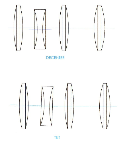
Hubble’s story really highlights how small deviations from the design shape can make a big difference in optical systems. In many optical systems, the tolerances can be quite close. There are several types of deviations in lens positions which affect the performance of the optic. These include, spacing, decenter, and tilt. Spacing is the obvious one, the tolerance in the space between optical elements. Tilt is the angle of the lens. Specifically, it’s the angle of the lens’s optical axis with respect to the axis of the device system. Last is decenter, which is how misaligned the optical axis is with the rest of the device.
As elements shift out of alignment in optical systems, image quality progressively decays. Unlike many mechanical designs where if parts are out of tolerance the device fails to function, the progressive degradation of optical systems makes defining failure points more difficult.
Solution: Analysis, Stack Reduction, and Adjustment
Like any tolerance stack issue the solution is always to set up the analysis. One method involves drawing a loop. In an optical system this loop is often between the optical axis of two lenses. A typical example tolerance loop starts with the optical axis of one lens, travels through the lens, then through the mounting interface between lens and housing, across the housing components, through the interface between the housing and the second lens, and then through the second lens. Each interface has a positioning tolerance. Each component has a surface-to-surface tolerance. Tolerance analysis is done by adding every tolerance in the loop. The analysis can be done statistically or worst case. Worst case tolerance analysis is generally more conservative than statistical tolerance analysis. One common mistake in tolerance analysis is inconsistent use of tolerance full range or plus-minus. Full range tolerances are sometimes used and are the maximum dimension minus the minimum dimension. More common is a plus/minus tolerance which assumes a nominal size in the middle. For locating tolerances radial clearances can be added to a plus minus tolerance and diametrical clearance can be added to a full range tolerance.
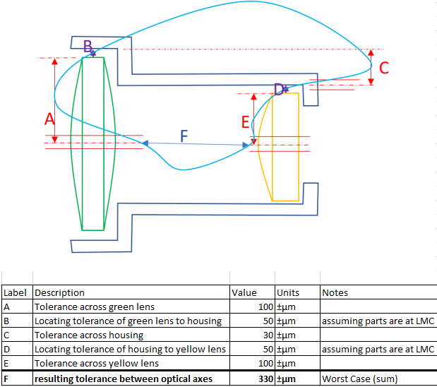
With the analysis in place, it becomes possible to quantify clever methods of reducing the tolerance stack. Removing components from a tolerance stack usually helps. Tolerance stacks can also be reduced by leveraging the strength of the manufacturing process of that part. For example, when using a molded part, tighter tolerances are maintained between features formed by the same half of the mold. While features formed by opposite sides of the mold will have tolerances of typically ±100 to ±150 µm (±4 to 6 thousandths of an inch), features formed in one side of the mold can hold tolerances of ±30 µm (±1 thousandth of an inch). The same can be said while machining. Features cut with the same tool and in the same setup will hold closer tolerances than features which require tool changes or re-fixturing the part.
The tolerance stack matters even when building a single prototype. Each part will deviate from the nominal shape to some degree. It’s important to establish how much deviation is acceptable for each part, and doing so will help ensure successful prototype builds.
Finally, as always with tolerances you get what you inspect not what you expect. If required tolerances are anywhere near the limit of the ability of the manufacturing process, measurement of parts will capture faults which might otherwise slip through.
In many optical designs, tolerance analysis reveals that an adjustment is necessary. There are many ways to achieve a spacing adjustment. A common technique involves rotating a single lens on a large diameter, fine pitch thread, such as an M12x1mm. In some products these threaded adjustments are adjusted once in the factory, using a thread-locking compound to secure the adjustment. In high precision, low volume applications, ultra-fine adjustment screws are available. These screws have very fine thread-pitch such as M3x0.1 or ¼-120. These screws are sold with a matching brass bushing with the mating screw thread. They also have a hardened steel or sapphire spherical tip, which improves the likelihood of achieving consistent contact.
Optical Systems Challenge #2: Managing Thermals
Many products, including optical products, need to operate in a wide variety of ambient environments. While some products sit on desks and remain between 20 and 25°C for their entire useful lives, many consumer products can see temperatures from -40°C to +60°C (-40°F to 140°F) in transit. Changes in temperature cause materials to expand and contract, which can destroy optical devices.
The first problem encountered with thermal expansion are changes in optical distances. Thermal expansion of a housing can and will shift the lens spacing. It can also change the focal lengths of lenses as the lens glass expands or contracts. This may cause an optic to lose focus when it changes temperature.
More importantly, however, is the damage that optical systems can incur through thermal expansion. Commonly used metal housings and optical glasses are rigid materials. Because they are rigid, stresses generated by a small change in component dimensions can be very high. These high stresses can lead to failures of the lens or housing. Bonded lenses may sheer their bond lines and fall out. Closely fit lenses can be fractured by thermally induced stresses.
Thermal expansion problems are particularly bad with rapidly changing temperatures. When temperatures change rapidly, some components will change temperature faster than others. In fact, certain areas of certain parts will change temperature faster than other areas of the same part. This can lead to thermally-induced warpage of components.
Even if stresses in lenses are low enough not to cause damage, they can cause stress-induced birefringence. Birefringence is a phenomenon where the index of refraction changes with polarization of light. Most of the time the light we see is randomly polarized. If the lens is birefringent, it will tend to blur randomly polarized light.
Solutions: Clearance and Material Selection
If quantified, problems associated with cracking lenses and sheering bonded interfaces can be avoided entirely. Those problems are generally solved using the accurate constraints described in the Mounting Lenses section. Essentially lens mounts should allow for the differences in thermal expansion and contraction between lenses and housing and allow enough clearance between components that they can expand, or contract as required. It’s important to note that not all parts will have the same temperature at the same time, so often extra clearance is required to allow separate parts to be at different temperatures.
Material selection is another way to avoid problems with thermal expansion. Optical glasses and metals can have similar coefficients of thermal expansion. However, some grow more than others. Metals like aluminum alloys expand about 20 to 24 millionths per degree C. Plain carbon steel expands about half as much. Many of the optical glasses are in the range of 5.3 to 9.6. One strategy to mitigate some of the negative effects of thermal expansion is to match the thermal expansion coefficients of the chosen materials. For example, Calcium Fluoride optics have very nearly the same thermal expansion coefficient as aluminum. Pyrex almost exactly matches brass. Invar, an alloy of steel and nickel, has almost no coefficient of thermal expansion, and can be used in designs which can’t tolerate thermal expansion.
Things to geek-out about!
- Stress bi-refringence was used for stress analysis before FEA became cheap. Models of parts were made from polycarbonate, and polished. A load representative load was applied to the model. Polarized light is then used to show bands of equal stress through the part.
- Prior to quartz clocks, pendulum clocks were the most accurate in the world. In the 1920’s the very best scientific pendulum clocks, such as the Shortt-Synchronome, had Invar pendulum rods to eliminate temperature effects. They also swung in vacuum chambers and pivoted on steel flexures to eliminate inaccuracies caused by pendulum friction and drag.
- Bimetallic strips use two metal strips with dissimilar coefficients of thermal expansion to sense temperature. Laminating the two strips together creates a component which curves or curls with a change in temperature. These are commonly used in thermostats.
Optical Systems Challenge #3: Mounting Lenses
Another mechanical challenge with designing optical systems is mounting the lenses into housings. Lenses are particularly difficult to hold on to. They are very rigid, and brittle, have complex curves and require accurate positioning. Furthermore, they have these delicate surfaces often with optical coatings which are susceptible to scratches. Many fastening techniques commonly used in machine design become difficult to apply. Threaded fasteners, press fits, and even snaps are all difficult or impossible to apply for lens mountings.
Screw and bolts are almost completely untenable in mounting optical elements, especially lenses. Lenses very rarely if ever have screw holes or similar mounting features. It just isn’t practical to grind holes into most optical materials. Furthermore, the high forces generated by threaded fasteners have the potential to crack or shatter glass lenses.
Press fits are also not very practical with optics. The outer diameter of a typical lens tends to have tolerances a little too loose for useful press-fits. Loose tolerances mean heavy presses or tricks like thermal shrink fitting. But with any of these processes the finished assembly usually has very high internal stresses, which can crack lenses.
Snap fits are another option which might make more sense with optics than threaded fasteners or press fits. But snap fits often require mating features, and lens manufacturing often doesn’t support inclusion of tabs, slots, lips, grooves or flats for engagement of a snap feature. Furthermore, snap features often require holes and slots in the part with the snap to allow the snap to deflect. These openings can be problematic for optics as they allow in contaminants, dust and stray light.
Solutions: Clamping, Bonding, Potting
There are, however, a number of solutions for mounting lenses. These include two methods: bonding, and clamping.
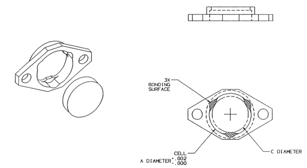
As you may have guessed, one of the most common methods for mounting a lens is with adhesives. Two methods of bonding are commonly used in optics: face bonding and edge bonding. Face bonding bonds the faces of the lens to a step in the housing. Edge bonding adheres the outer, typically cylindrical, edge to the housing. Face bonds and edge bonds both typically take advantage of limited, discrete areas where the adhesive is applied. Applying the adhesive in shallow recesses leaves datum surfaces clear of adhesive for accuracy, and controls adhesive thickness. In face-bonded applications, shims can be used around the outer diameter of the lens to center the lens in the bore while allowing clearance for thermal expansion. The required bond area is affected by how the adhesive will be loaded. In a face-bonded system, the adhesive is generally loaded in tension, whereas in an edge-bonded application the adhesive is generally loaded in shear. Most adhesives are substantially stronger in shear than in tension. As with any adhesive application, proper selection of the adhesive for the substrate materials is critical. Similarly, proper cleaning and surface preparation of the parts also helps ensure a good bond. When mounting lenses, UV-curing adhesives are often a good choice. They can usually be cured with UV light transferred right through the lenses.
Another way to mount lenses is to clamp them in place. This can be done with large diameter threaded rings, or machined parts which screw onto housings. In either case the lens is sandwiched between rigid datum surfaces and a compliant material. Use of a compliant material allows the lenses to slip ever so slightly without building up large forces as temperatures change. O-rings are often used for the compliant surface.
Many older designs “pot” lenses in place with a large amount of adhesive around the edges of the lens. This process can create a tightly sealed optic and hold the lenses very securely, however there are greater risks of mis-locating the optic with adhesive between the lens and its reference surface. Potting also all but eliminates the possibility of rework on the optical assembly, increases risks of damage due to thermal expansion.
Optical Systems Challenge #4: Dust, Humidity, Contaminants
Many mechanical systems are quite robust to dust, dirt, condensation, and contamination however optics are not. Optical performance is rapidly degraded by condensation, dirt, and dust. The outer surfaces of the outermost lenses are often fairly easily cleaned; however, the surfaces inside an optical system often impossible to clean. Dust and dirt reduce the clarity of the optic, while condensation can blind the optic completely. Furthermore, there can be contamination from within the optic. Some materials such as adhesives, rubbers or plastics can out-gas. The out-gassed material can condense permanently on the optical surfaces, clouding the optic.
Solution: sealed optics and material selection
Most of the contaminates like dust and dirt can be managed by sealing the optics. Many optical systems today are made waterproof. The challenge of waterproof optics is similar to all other waterproof devices. Elastomeric seals must retain adequate compression under all circumstances, and at all positions. Dispensed sealants and adhesives must undergo careful process development to ensure every assembly is adequately sealed. Making a system waterproof also almost always makes it air-tight. Changes in atmospheric pressure result in pressure within the device. Either the device has to vent this pressure or be robust to it. Of particular concern is descent while in airfreight where pressure increases from about 10 psi to 14-15 psi. If the device is vented, there will be an influx of air into the device, and that air can bring whatever contaminants are in it into the device.
To prevent internal condensation, it’s often helpful to build assemblies in a dry environment. If the optical assembly is built in a cold space or a de-humidified space, it can greatly reduce the likelihood of condensation appearing on the inside optical surfaces.
One of the most catastrophic types of contamination is related to outgassing. To prevent outgassing materials from condensing on the inside surfaces of an optic, it’s important to understand the working temperature limits of your materials and how they fail at those temperatures. O-rings used in sealed and clamp-mounted optics are of particular concern. They are not problematic at lower temperatures, but if service temperatures rise, they can cause outgassing issues. In some applications, such as high-powered lasers, the optics can actually reach fairly high service temperatures. In these applications it’s often necessary to eliminate plastics, adhesives, and rubbers from the design completely. Clamped lens assemblies can still be achieved without o-rings by using metal flexures. Springs can be used to hold lenses in place. Elastic metal seals intended for EMI shielding make for useful o-ring replacements in high temperature applications.
Conclusion
Developing optical products is more important than ever, however optics pose unique and complex challenges. The challenges include designing for close tolerances, managing thermal expansion of different materials, holding curved and delicate lenses, and keeping out dust and contaminates. Each of these is a serious challenge which if not addressed properly can cause a product to fail. However, these challenges can be nicely addressed with good engineering. Tolerance analysis reveals the severity of tolerance stack-up, and guides solutions including tolerance stack reduction and addition of adjustment processes. Thermal expansion can be controlled by matching the thermal expansion of different materials, allowing parts to float slightly, or selecting materials with very low thermal expansion. Mounting curved, delicate lenses can be accomplished with adhesives or clamping them with a compliant component. Dust, dirt and contamination can be managed by sealing up optical devices, assembling in a dry-air environment, and eliminating materials which out-gas at the device’s operating temperatures. All these technical challenges have technical solutions.
Designing optical systems shouldn’t intimidate mechanical engineers! Sure, there are challenges, but those challenges are why many engineers got into mechanical engineering in the first place. There is nothing magic in the design of optical systems.

